Durability Assessment of Motors Based on Temperature and Power Data in Endurance Testing
Introduction
As EVs and industrial equipment continue to evolve toward higher performance, motors are required to operate reliably under high-load conditions for extended periods without failure. To ensure product reliability, durability testing under conditions close to actual use is essential. However, since motors are subject to various factors such as load fluctuations, temperature increases, and electrical stress, any one indicator can’t be used to accurately detect deterioration.
Challenges in motor durability testing
Motor durability testing involves the following challenges:
- Difficulty in detecting electrical changes (instantaneous fluctuations, harmonic distortion, and efficiency degradation).
- Difficulty in seeing the relationship between the motor’s electrical characteristics and temperature fluctuations in motor windings, housings, and peripheral equipment.
- Absence of a system for synchronized, long-term data collection.
Solution
By combining Hioki's high-precision power analyzers with temperature measurement loggers, motor durability testing can be conducted with a simple setup.
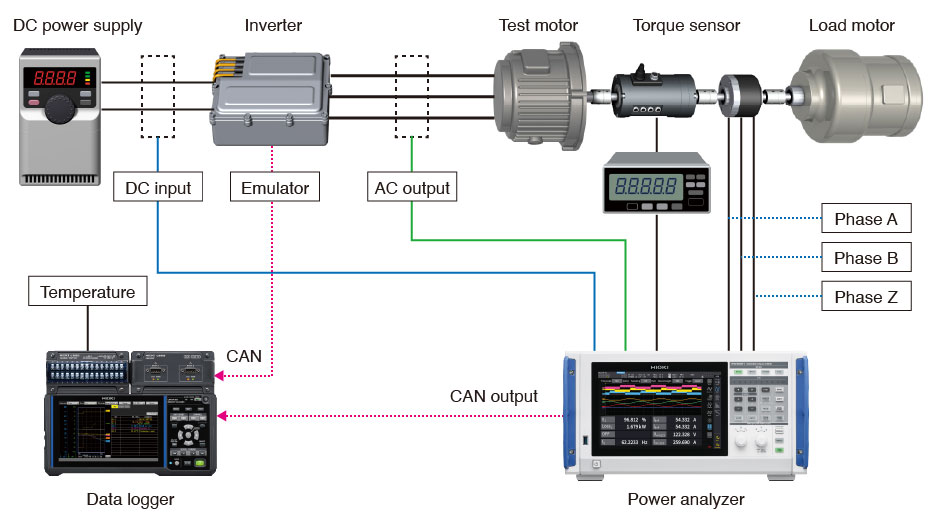
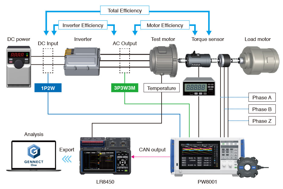
Using the LR8450 data logger, temperatures of peripheral equipment and components can be measured, while parameters of inverters and motors can be measured using the PW8001 or PW4001 power analyzers. The PW8001 and PW4001 power analyzers feature CAN output functionality, enabling measured parameters to be aggregated onto the LR8450 data logger via CAN communication* for synchronized measurements. If the inverter emulator also has CAN output functionality, control signals can be monitored with the data logger as well. By continuously and stably recording changes in power and temperature over an extended period, signs of motor deterioration can be swiftly detected.
- *1:The CAN Unit U8555, an optional accessory for the LR8450, enables CAN data logging at intervals as fast as 10 ms.
Benefits of this solution
- Changes in voltage and current balance
- Subtle fluctuations in efficiency
- Trends in harmonic components
1. Continuous high-precision monitoring of motor electrical stress
- Motor winding temperatures
- Housing temperatures
- Temperatures of peripheral equipment, including bearings and cooling water
2. Accurate logging of temperature trends
- Event recording using the data logger’s trigger function
- Integrated analysis of data via CSV files
3. Correlation analysis of electrical and temperature data
Example measurement
Actual measurements were conducted using Hioki’s motor bench.
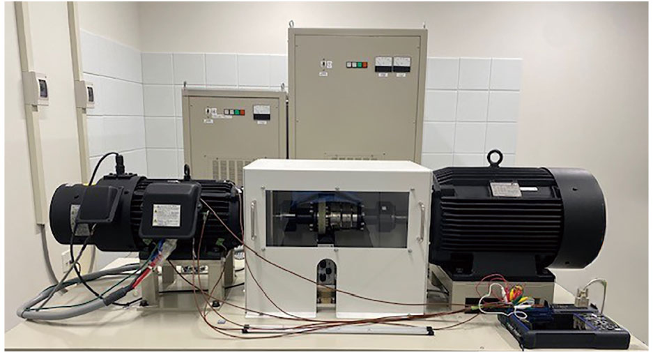 Layout
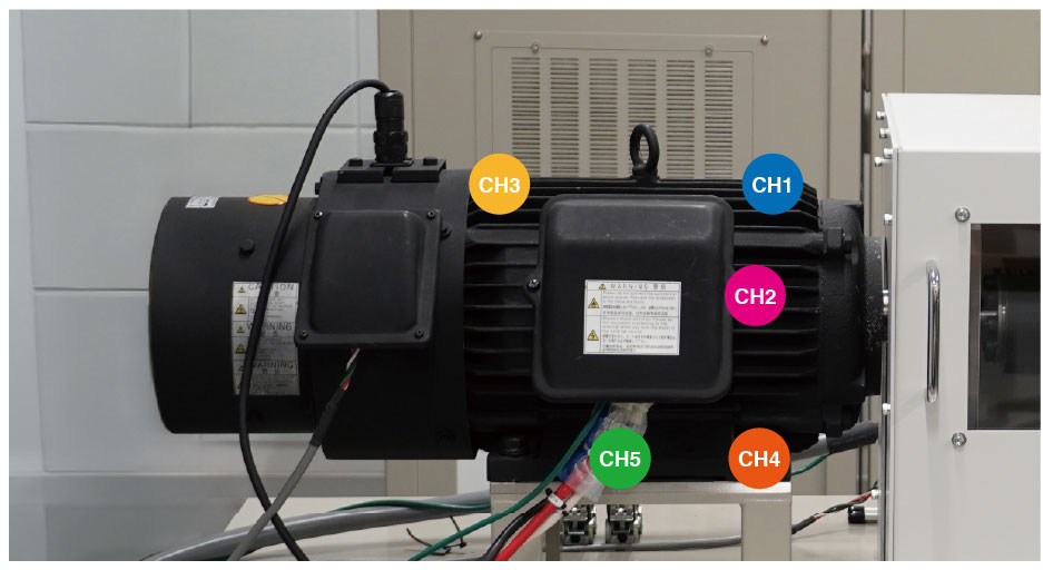 Motor temperature measurement points
List of equipment used
| Equipment Name | Quantity | Item Name |
|---|---|---|
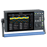
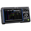
| LR8450 | ×1 | MEMORY HiLOGGER |
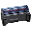
| U8551 | ×1 | UNIVERSAL UNIT |
| thermocouple with shield | ×5 | ― |
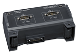
| U8555 | ×1 | CAN UNIT |
| CAN cable | ×1 | ― |
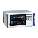
| PW8001-13 | ×1 | POWER ANALYZER |
| U7005 | ×4 | 15MS/S INPUT UNIT |
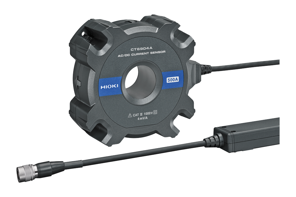
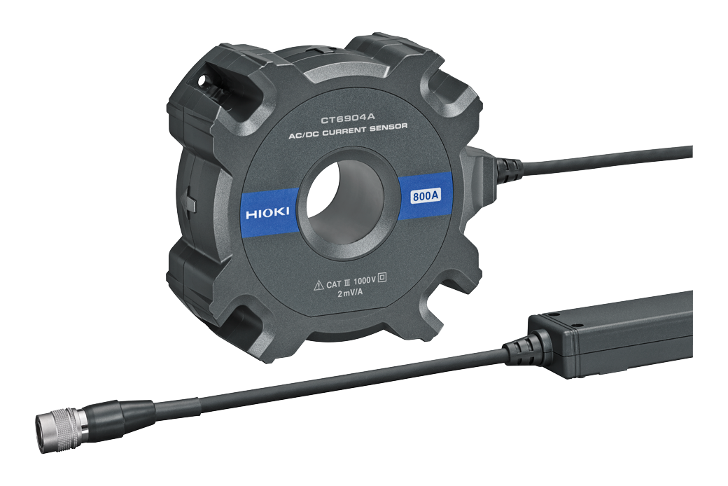
| CT6904A | ×4 | CURRENT SENSOR |
DUT information
| Item | Details |
|---|---|
| Test Motor | Fuji Electric Co., Ltd. GNF2117A |
| Inverter | Myway Plus Inc. MWINV-5044-SIC SIC Vector Control |
Measurement Conditions
- Motor operated at a constant speed of 1000 rpm
- SiC inverter with a switching frequency of 10 kHz
- Data update rate of 10 ms
- Continuous operation is performed for approximately 2 hours
- Measurement parameters from the PW8001 are output via CAN and collected using the LR8450
Temperature measurement considerations
High-frequency switching in the inverter generates electromagnetic noise in its vicinity.
This noise can cause instability in the measured temperature values.
Therefore, appropriate noise countermeasures are required, such as using shielded temperature sensors (thermocouples) and configuring the filter settings of the measurement instrument.
In this measurement, shielded thermocouples are used for temperature monitoring. The shield is connected to the motor chassis to strengthen the grounding and improve noise resistance.
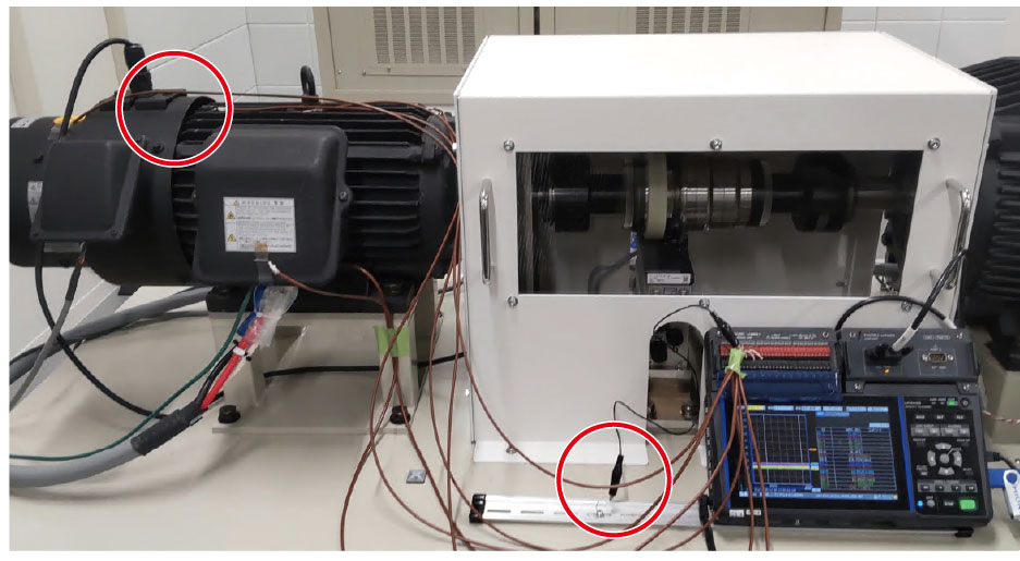 Shielded thermocouple setup
In addition, the data update interval of the U8551 unit is set to 1 second via the LR8450, and the digital filter is enabled to attenuate high-frequency noise components above 60 Hz.
LR8450 filter settings
| Power supply frequency filter setting | Wire break detection setting | Data refresh interval | |||||||||
|---|---|---|---|---|---|---|---|---|---|---|---|
| 10 ms | 20 ms | 50 ms | 100 ms | 200 ms | 500 ms | 1 s | 2 s | 5 s | 10 s | ||
| 60 Hz | Off | 20.8k | 6.94k | 2.98k | 2.37k | 739 | 60 | 60 | 60 | 60 | 60 |
| On | – | 20.8k | 6.94k | 2.98k | 2.37k | 739 | 60 | 60 | 60 | 60 | |
| 50 Hz | Off | 20.8k | 6.94k | 2.98k | 2.37k | 739 | 50 | 50 | 50 | 50 | 50 |
| On | – | 20.8k | 6.94k | 2.98k | 2.37k | 739 | 50 | 50 | 50 | 50 | |
–: Setting not available
Unit: Hz
Key points for inverter measurement
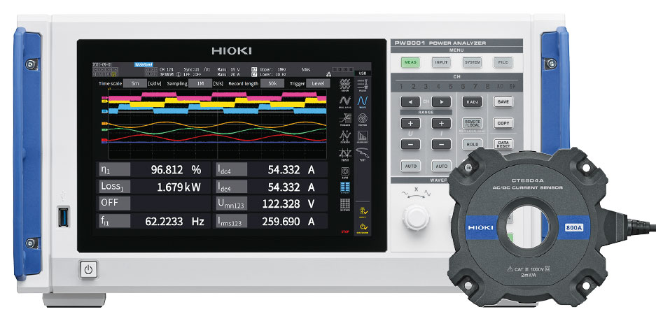
Since the inverter output power contains high-frequency components and exhibits a low power factor, a power analyzer and current sensors capable of accurately measuring the switching frequency and its harmonic components are required. For measuring a SiC inverter, the combination of the PW8001 and CT6904A, which offers superior bandwidth and phase characteristics, is recommended. Hioki’s high precision/accuracy power analyzer PW8001 and current sensor CT6904A
Please also refer to the application note, “Comparison of SiC Inverters Measured by High-End Power Analyzers”.
Evaluation criteria
- 1.The rotational speed of the motor during steady-state operation was 1000 rpm ±50 rpm.
- 2.The temperature at various measurement points of the motor did not exceed 50°C.
- 3.Efficiency variation during steady-state operation remained within ±5%.
- 4.Additionally, no abrupt changes in torque or motor power fluctuation were observed.
Measurement results
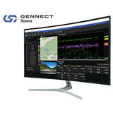
The data recorded using the logger was analyzed with Gennect Space.
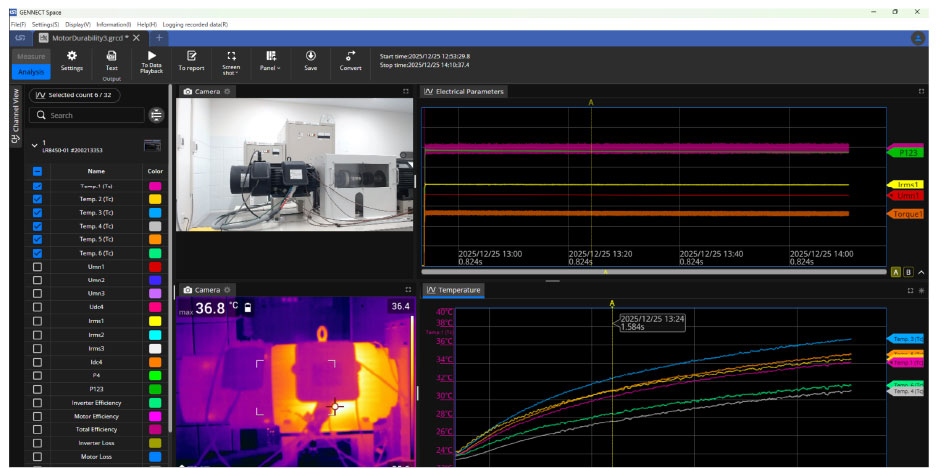
Relationship between temperature and efficiency
During durability testing, the motor’s behavior is recorded not only as measurement data but also as video footage and thermal images captured with a thermal camera.
Gennect Space synchronizes motor speed, torque, efficiency, and temperature data with visual and thermal recordings on a single time axis and stores them as a single dataset. If an abnormal event, such as unusual noise, smoke, or even motor burnout, occurs during long-term testing, engineers can precisely review what happened at that exact moment by replaying synchronized measurement data and video side by side. This makes it possible to correlate numerical changes with physical behavior and thermal patterns, something that cannot be achieved with data or video alone.
As a result, durability testing goes beyond simple pass/fail judgment. By preserving when, how, and under what conditions an abnormality developed, Gennect Space enables durability evaluations to serve as clear, objective evidence for root-cause analysis and reliability assessment
Conclusion
By combining Hioki’s power analyzers with data loggers, it is possible to construct a simple testing environment that enables high-precision and simultaneous tracking of electrical stress and temperature changes in motors, ensuring reliable detection of deterioration signs.
For detailed product information, please visit our website.
For a demonstration or consultation on a specific application, please contact us.
Reference
- Applications : Comparison of SiC Inverters Measured by High-end Power Analyzers
- Applications : Automatically detect abnormalities during durability testing