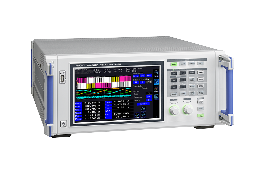
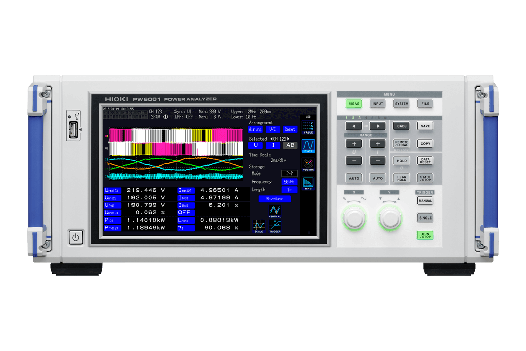
POWER ANALYZER PW6001
DC, 0.1 Hz to 2 MHz, 3-phase 4-wire, High Precision Power Analyzer for Motor and Inverter Efficiency Analysis
Discontinued
Product Video
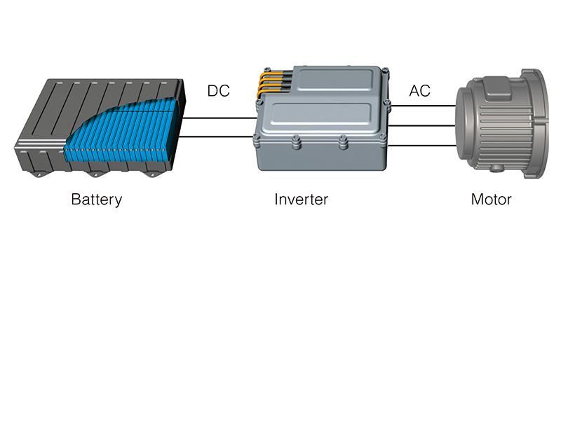
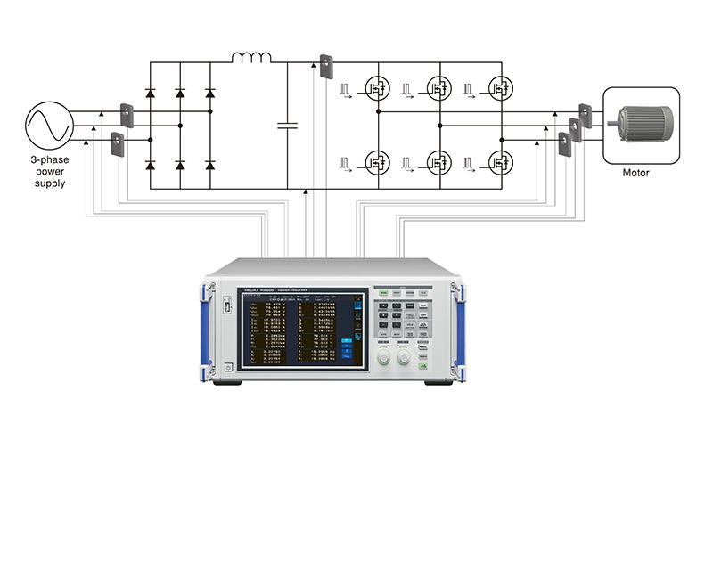
Hioki benchtop power meters and power analyzers are best in class power measuring instruments for measuring single to three-phase lines with a high degree of precision and accuracy. The PW6001 is Hioki’s flagship power analyzer, featuring high accuracy, wide band, and high stability for measuring electrical power from DC to inverter frequencies, providing maximum of 12 channels (*1) to support single- and three-phase inverter motor system measurements and next generation devices such as silicon-carbide (SiC) inverters.
Key Features
- Exclusive current sensor phase shift function lets you maintain accuracy even in high frequency, low power factor applications
- Basic accuracy of ±0.02% (*2) for power measurement
- High noise resistance and stability (80 dB/100 kHz CMRR, ±0.01%/°C temperature characteristics)
- Accurate measurement even when the load is characterized by large fluctuations; TrueHD 18-bit resolution
- 10 ms data refresh while maintaining maximum accuracy (*3)
- DC accuracy of ±0.07%, which is key for stable, accurate efficiency measurement
- Wide frequency bandwidth of DC, or 0.1 Hz to 2 MHz
- Achieve true frequency analysis with high-speed 5MS/s sampling (18 bit)
- Synchronize 2 units for up to 12 channels (*4) in real time
- Special triggers to enable waveform analysis and motor analysis without the need for an oscilloscope
- Wideband harmonic analysis up to the 100th order with a 1.5 MHz band
- Send measured values to Hioki data loggers using a Bluetooth® wireless technology compatible adapter (LR8410 Link-compatible products).
- Earning Japan Calibration Service System (JCSS) Certification for DC Power Measurement. (*5)
- *1:When synchronizing two 6-channel models connected via optical link.
- *2:PW6001 accuracy only. Instrument delivers accuracy of ±0.07% even after the current sensor accuracy has been added.
- *3:Using a specially designed IC to make all measurements independently while performing simultaneous calculations.
- *4:Two 6-channel models can be connected with an optical connection cable
- *5: JCSS is standard that is satisfy the requirements of the ISO/IEC 17025 international standard.
Learn more
Model No. (Order Code)
| PW6001-01 | 1ch |
|---|---|
| PW6001-02 | 2ch |
| PW6001-03 | 3ch |
| PW6001-04 | 4ch |
| PW6001-05 | 5ch |
| PW6001-06 | 6ch |
| PW6001-11 | 1ch, motor analysis, D/A output |
| PW6001-12 | 2ch, motor analysis, D/A output |
| PW6001-13 | 3ch, motor analysis, D/A output |
| PW6001-14 | 4ch, motor analysis, D/A output |
| PW6001-15 | 5ch, motor analysis, D/A output |
| PW6001-16 | 6ch, motor analysis, D/A output |
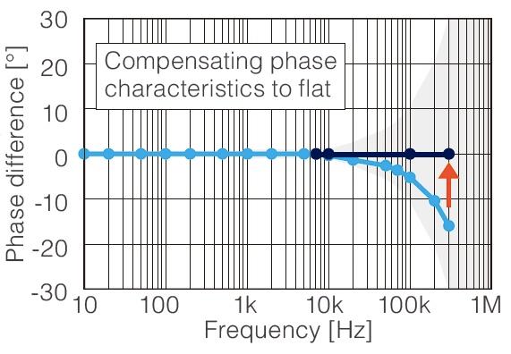
Current Sensor Phase Shift
Current sensor phase shift is essential especially in high current situations in order to achieve optimal measurement precision. Current sensors typically exhibit gradually increasing phase error in the high-frequency region due to the characteristics of the sensor’s magnetic core and circuitry. Furthermore, differences in the design of various sensor models cause the magnitude of this error to vary.
The PW6001’s current sensor phase shift function uses sensor-specific phase error information to correct for error, thereby improving phase characteristics in the high-frequency region and reducing power measurement error. Phase shift correction is conducted with a 0.01° resolution in order to measure power even more accurately.
0.1 Hz to 2 MHz frequency bandwidth
Power measurements across wide bandwidths are required for supporting high-speed switching devices such as SiC. Compared even to the Hioki 3390 Power Analyzer, the PW6001 is engineered with 10x the frequency band and sampling performance.
High accuracy, wideband, and high stability. The Hioki PW6001 combines the 3 important elements of power measurement and basic performance backed by advanced technology to achieve unsurpassed power analysis.
High-speed sampling of 5 MS/s for true frequency analysis
Measurements based on sampling theorem are required to perform an accurate power analysis of PWM waveforms. The Hioki PW6001 features direct sampling of input signals at 5 MS/s, resulting in a measurement band of 2 MHz. This enables analysis without aliasing error
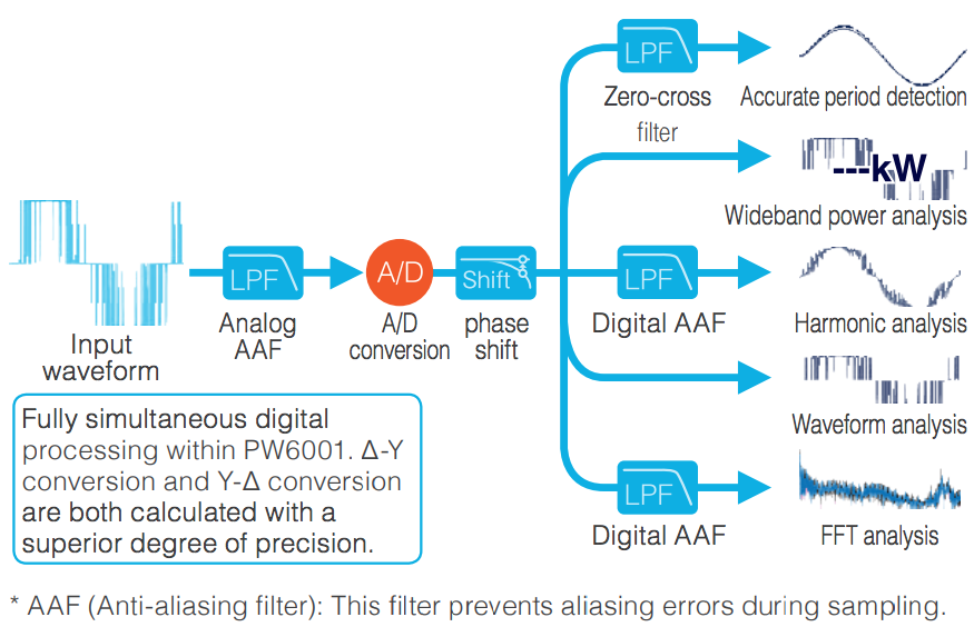
Fast, simultaneous calculation functions achieved with Power Analysis Engine II
All measurements, including period detection, wideband power analysis, harmonic analysis, and waveform analysis, are digitally processed independently and with no effect on each other. Fast calculation processing is used to achieve a data update speed of 10 ms while maintaining maximum
accuracy.
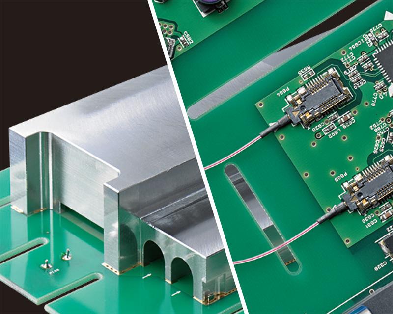
Strengthened resistance to noise and temperature fluctuations in the absolute pursuit of measurement stability
The custom-shaped solid shield made completely of finely finished metal and optical isolation devices used to maintain sufficient creepage distance from the input terminals dramatically improve noise resistance, provide optimal stability, and achieve a CMRR performance of 80 dB/100 kHz. Add the superior temperature characteristics of ±0.01%/°C and you now have access to a power analyzer that delivers top-of-the-line measurement stability.
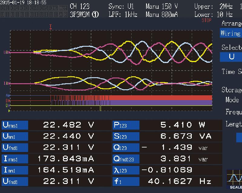
Analyze waveforms without an oscilloscope
In addition to voltage and current waveforms, torque sensor and encoder signals can also be displayed simultaneously. The PW6001 is also built in with triggers, pre-triggers, other triggers convenient for motor analysis such as for PWM waveforms, as well as encoder pulse triggers.
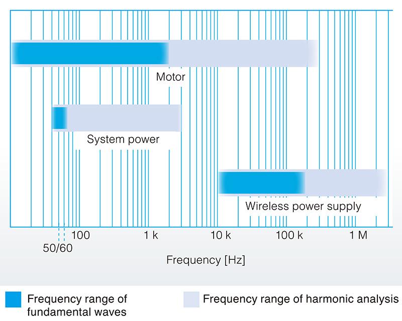
Harmonic analysis up to 1.5 MHz
Wideband harmonic analysis is provided as a standard feature to a max. 100th order for fundamental frequencies 0.1 Hz to 300 kHz and an analysis band of 1.5 MHz. Analysis of fundamental waves in motors and measurement of distortion rate in the transmission waveforms for wireless power supplies
are now possible.
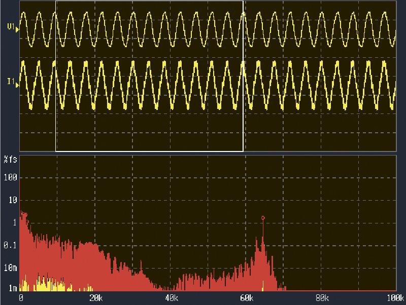
FFT analysis of target waveforms
Frequency analysis up to 2 MHz. Specify any waveform analysis range you like and see the 10 highest peak values and frequencies displayed.
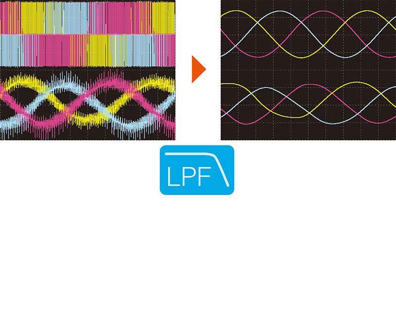
Digital LPF for displaying the waveform you want to view
Select a cutoff frequency for the measurement target. Digital LPF greatly reduces noise to let you display the waveform you want to view.
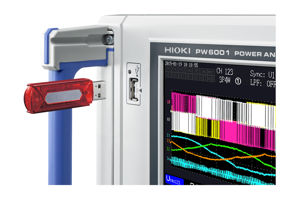
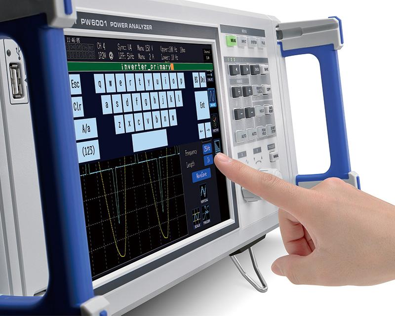
Seamless operability
Time spent on operations is reduced, to allow focused concentration on analysis.
-9-inch touch screen with soft keypad
-Dual knobs for vertical/horizontal manipulation of waveforms
-Wiring confirmation function, to avoid wiring mistakes
-Enter handwritten memos on the screen, or use the onscreen keypad
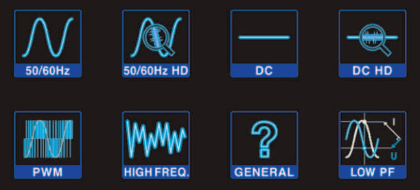
One-touch settings take you to measurement immediately
The built-in easy setup function allows you to simply select the type of measurement line and immediately start measurement using the automated optimum settings.
DC accuracy is indispensable for achieving correct efficiency measurements
For example, when measuring the efficiency of a DC/AC converter, not only AC accuracy but also DC accuracy are equally important. With the PW6001, a DC measurement accuracy of ±0.02% rdg. ±0.05% f.s.* delivers correct and stable efficiency measurements.
*Unit accuracy only
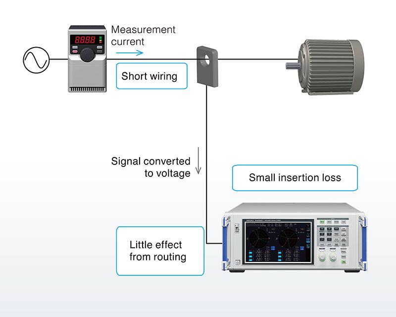
Specially designed for current sensors to achieve highly precise measurement
This reduces the effects of wiring and meter loss, allowing measurements with wiring conditions that are close to the actual operating environment for a highly efficient system.
- Short wiring
- Little effect from routing
- Small insertion loss
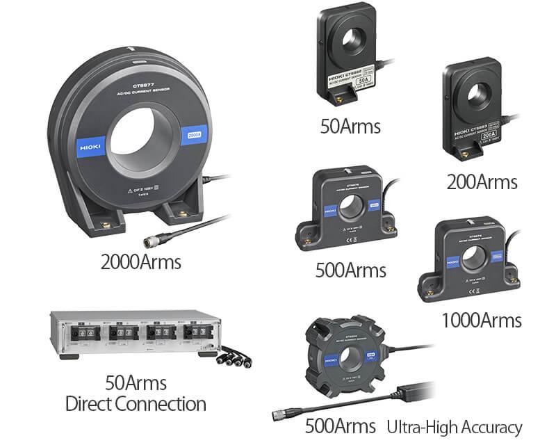
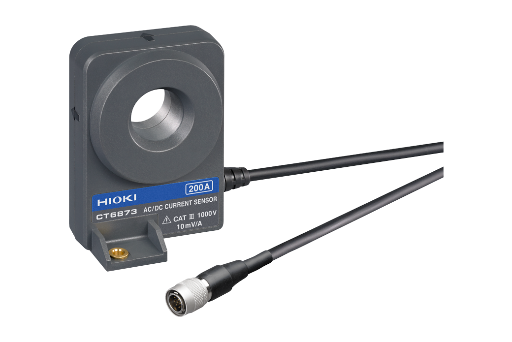
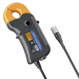
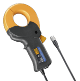
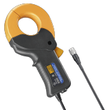
High-accuracy clamp current sensor
The CT684x series feature broad temperature characteristics and an operating temperature range of -40°C to 85°C, allowing them to be used in operational evaluations of devices and inside equipment that are subject to extreme temperature changes. The current sensors’ tough performance helps ensure you can make the measurements you need.

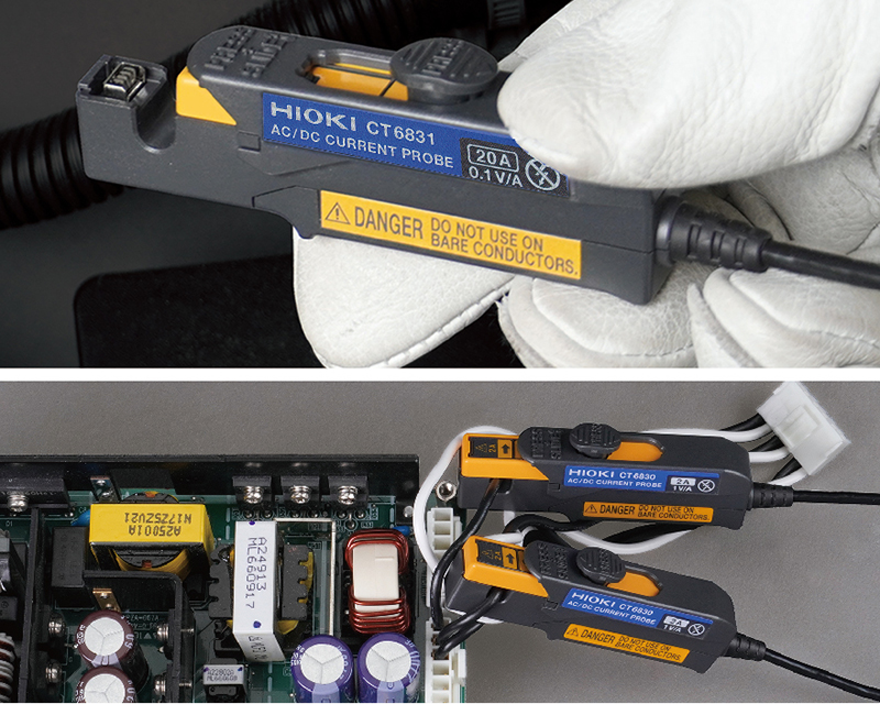
Easy installation even in complicated wiring or narrow/tight spaces
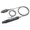
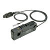
The AC/DC Current Probe CT6830 and CT6831 (optional) have a compact and small-size design, making it easy to install in tight spaces around circuit boards, such as the switching power supplies inside products. Furthermore, they cover a wide operating temperature range from -40°C to 85°C, allowing for accurate measurement of low-level DC currents even in environments where the ambient temperature varies.
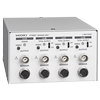
Get a combined accuracy of ±0.075% rdg. with CURRENT BOX PW9100
Add ±0.05% rdg. accuracy of the current sensor to the PW6001’s basic accuracy of ±0.025% rdg. to achieve accuracy of ±0.075%. Choose from a diverse array of sensors to cover very small currents from 10mA up to large 2000A* loads.
*Effective measurement range.
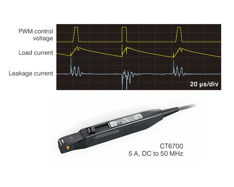
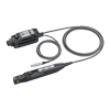
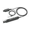
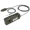
Wideband current probes supported
When combined with the Hioki wideband current probes, it is also possible to measure minute currents of 0.5 mA. This is perfect for observing leakage current waveforms in inverters.
・CT6700, CT6701 1 mA〜
・CT6710, CT6711 0.5 mA〜
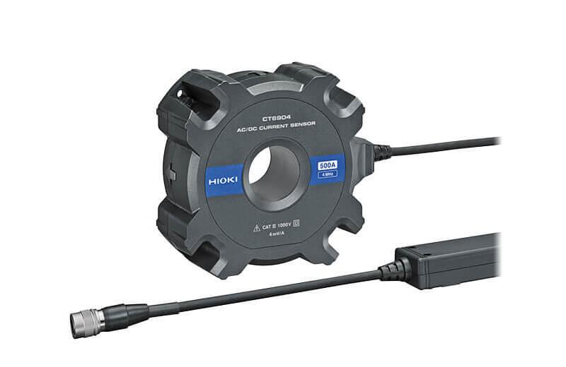
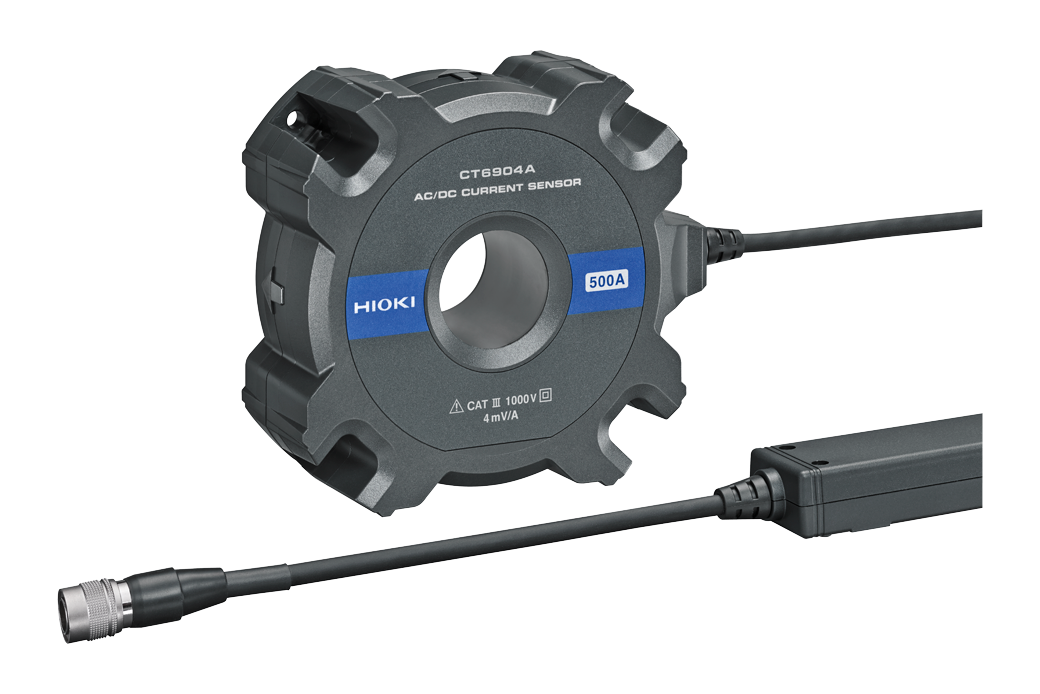
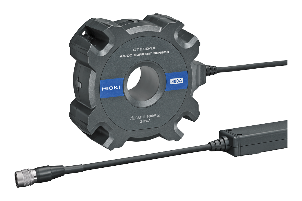
CT6904, The optimal device for testing large current inverters
Newly developed opposed split coil technology is used in winding (CT) areas, achieving a wide measurement range from DC to 4MHz.
The CT6904 makes it a world-class current sensor that provides the ultimate level of performance when used in conjunction with the Power Analyzer PW6001.
(The sensor is also available in an 800 A rated version.)
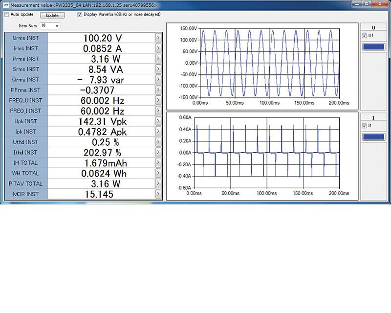
PC Communication Software – PW Communicator
PW Communicator is an dedicated application software for communicating between a PW6001 power meter and a PC. Free download is available from the Hioki website. The application contains convenient functions for setting the PW6001, monitoring the measurement values, acquiring data via communication, computing efficiency, and much more.
Remote control via LAN
Control the PW6001 remotely from a tablet, smartphone, or any device offering a standard web browser.

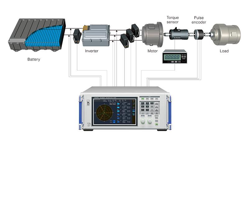
Diverse motor analysis functions
Enter signals from torque meters and speed meters to measure motor power. In addition to motor parameters such as motor power and electrical angle, output signals from insolation meters and wind speed meters can also be measured.
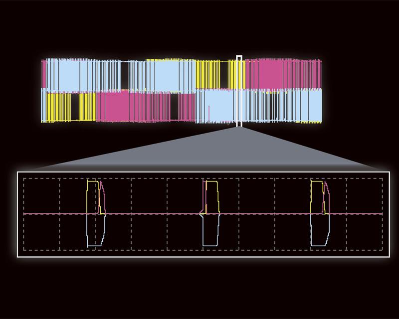
SiC measurement achieved with high resolution
High resolution is required for the high precision measurement of PWM waveforms for SiC semiconductors with low ON resistance. TrueHD 18-bit is achieved at a level of precision that has never been seen before.
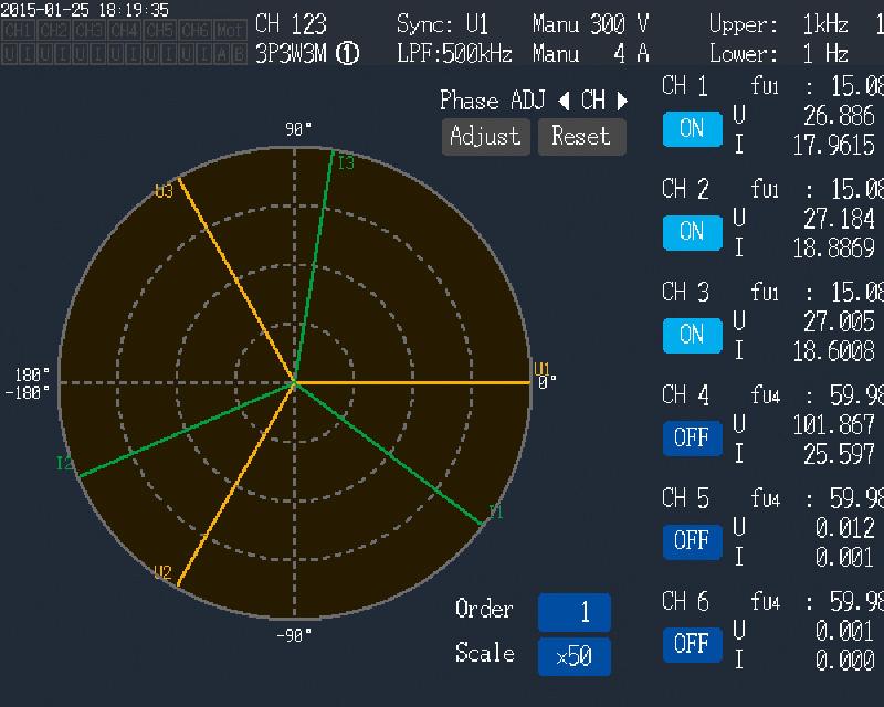
Advanced electrical angle measurement function
The PW6001 features a built-in electric angle measurement function required for the measurement of motor parameters in high-efficiency synchronized motors and the analysis of vector control via dq coordinate systems. Make real-time measurements of phases for voltage and current fundamental wave components based on encoder pulses. Further, zero-adjustment of the phase angle when induced voltage occurs allows phase measurement at the induction voltage standard. Finally, the PW6001 can detect the forward/reverse from A phase and B phase pulses to enable 4-quadrant analysis of torque and RPM.
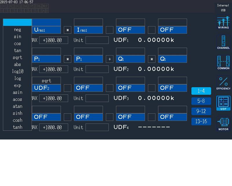
Display any calculation result in real-time
Set equations to have PW6001 compute measurement values in the way you want. You can enter up to 16 calculation formulas, and functions like sin and log are supported. Calculation results can be used as parameters for other calculation formulas, enabling complex analysis.
-Calculate Ld and Lq in motor vector control
-Measure ferrite core loss
-Add up RMS and power
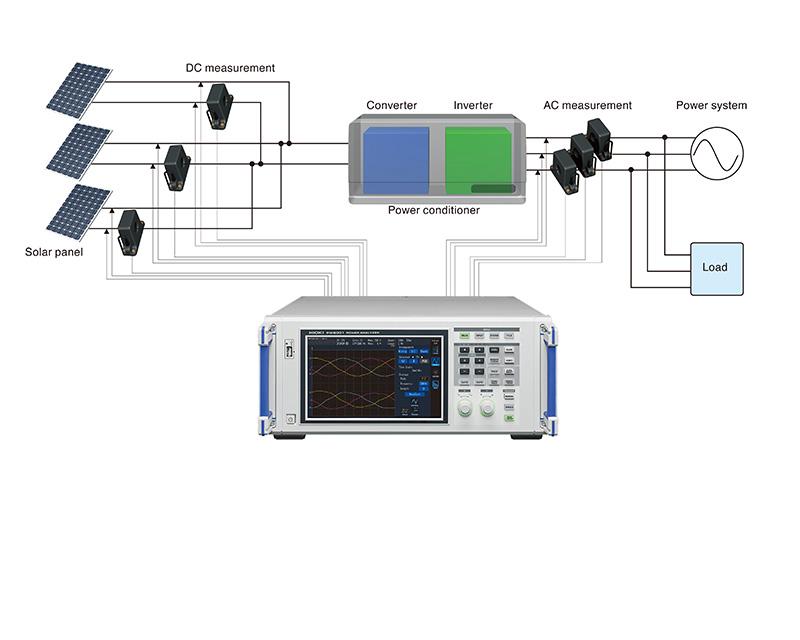
-Calculate multisystem efficiency and loss with solar power modules and similar equipment
Power conditioner testing
Parameters required for power conditioners, such as fundamental wave reactive power Qf nd, DC ripple rate, and 3-phase unbalanced rate, can be measured and displayed simultaneously. The required measurement data can be viewed at a glance, improving test efficiency.
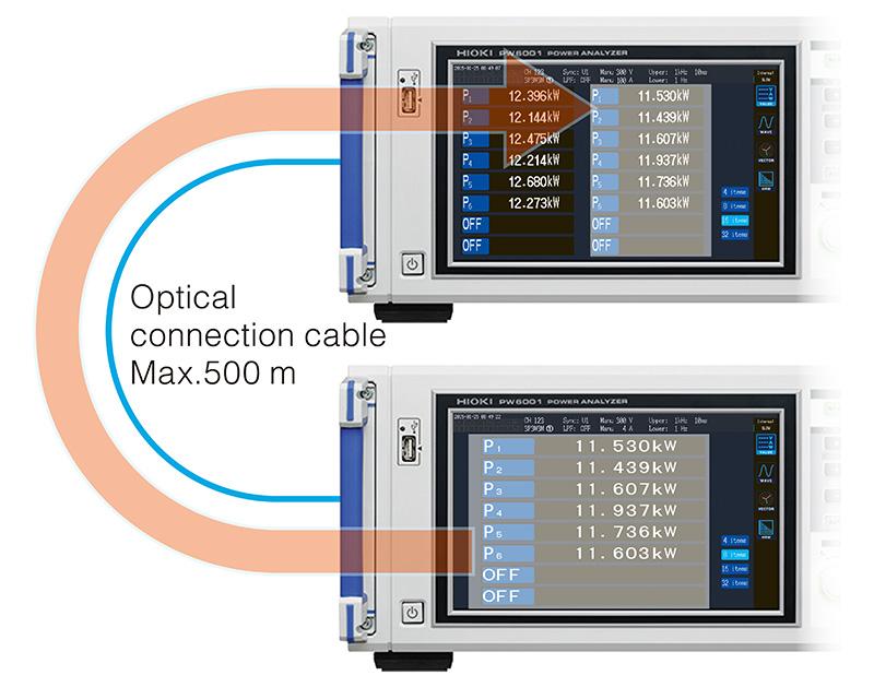
Build a 12-channel power meter using “numerical synchronization”
For multi-point measurements, use the numerical synchronization function to transfer power parameters from the secondary device to aggregate at the primary in real-time, essentially enabling you to build a 12-channel power analysis system
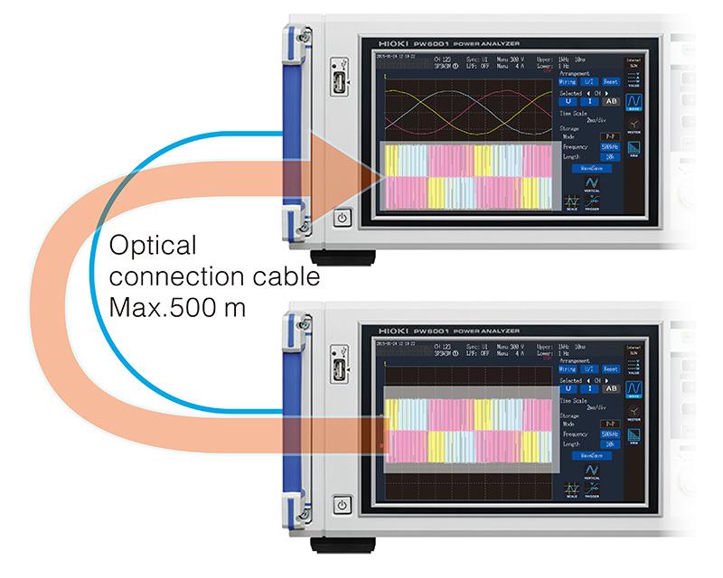
Simply transfer waveforms with “waveform synchronization”
Achieve real-time* transfer of 5 MS/s 18-bit sampling data. Measurement waveforms on the secondary instrument are displayed without modification on the primary unit, paving the way for new applications for power analyzers, such as measurement of the voltage phase difference between two separate devices.
* For both primary instruments and secondary instrument, waveform synchronization operates only when there are 3 or more channels. Max. ±5 sampling error
Basic specifications
| Measurement line type | Single-phase 2-wire, single-phase 3-wire, three-phase 3-wire, three-phase 4-wire | |||||
|---|---|---|---|---|---|---|
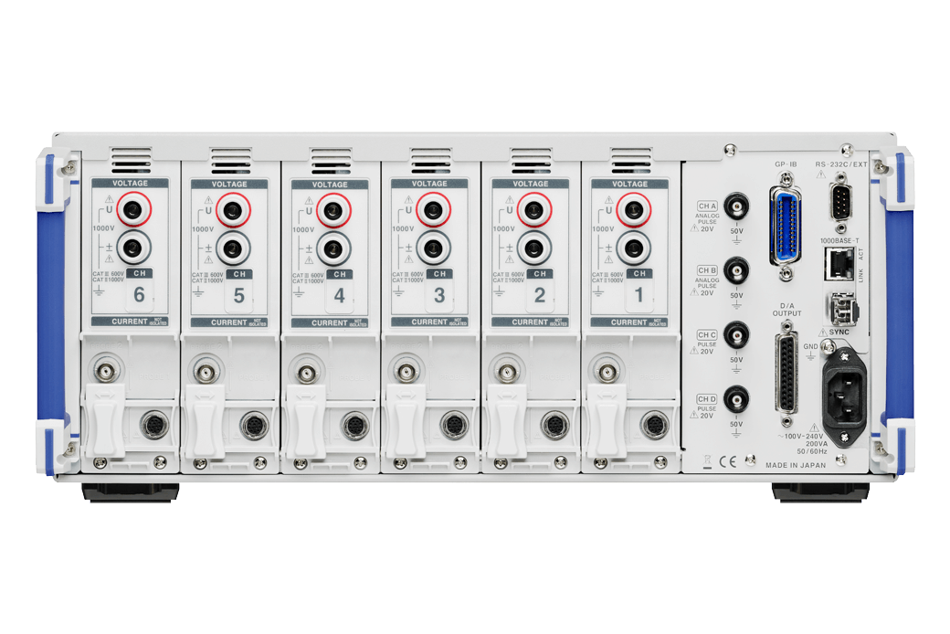
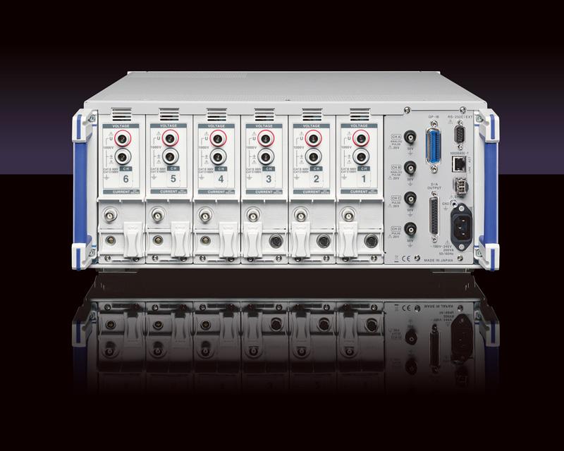
| Number of input channels | Max. 6 channels; each input unit provides 1 channel for simultaneous voltage and current input (Voltage measurement unit: Photoisolated input, resistance voltage divider, Current measurement unit: Isolated input from current sensor) |
|||||
| Measurement items | Voltage (U), current (I), active power (P), apparent power (S), reactive power (Q), power factor (λ), phase angle (φ), frequency (f), efficiency (η), loss (Loss), voltage ripple factor (Urf), current ripple factor (Irf), current integration (Ih), power integration (WP), voltage peak (Upk), current peak (Ipk) | |||||
| Harmonic measurement: Harmonic active power, select calculation order from 2nd order to 100th order |
||||||
| Waveform recording: Voltage and current waveforms/ Motor pulse: Always 5 MS/s Motor waveforms: Always 50 kS/s, 16 bits Recording capacity: 1 Mword × ((voltage + current) × number of channels + motor waveforms) |
||||||
| Motor analysis (PW6001-11 to -16 only): Voltage, Torque, Rotation, Frequency, Slip, or Motor output | ||||||
| Measurement range | Voltage range: 6 to 1500 V, 8 ranges Current range (Probe 1) : 400 mA to 1 kA (depends on current sensor) Current range (Probe 2) : 100 mA to 50 kA (depends on current sensor) Power range: 2.40000W to 4.50000MW (depends on combination of voltage and current range) Frequency range: 0.1 Hz to 2 MHz |
|||||
| Basic accuracy | Voltage: ±0.02 % rdg. ±0.02 % f.s. Current: ±0.02 % rdg. ±0.02 % f.s. Active power: ±0.02 % rdg. ±0.03 % f.s. |
|||||
| Synchronization frequency range | Power measurement: 0.1 Hz to 2 MHz Harmonic measurement: 45 Hz to 66 Hz (IEC standard mode), 0.1 Hz to 300 kHz (Wideband mode) |
|||||
| Frequency band | DC, 0.1 Hz to 2 MHz | |||||
| Data update rate | Power measurement: 10 ms/ 50 ms/ 200 ms Harmonic measurement: 200 ms (IEC standard mode), 50 ms (Wideband mode |
|||||
| Data save interval | OFF, 10 msec to 500 msec, 1 sec to 30 sec, 1 minute to 60 minutes User-selected from all measured values, including harmonic measured values, Specified measured values can be saved in internal memory or USB flash drive |
|||||
| External interfaces | USB (memory), LAN, GP-IB, RS-232C (for communication/LR8410 link), External control ,Synchronization control | |||||
| Logger connectivity | Sends measured values wirelessly to logger by using a Bluetooth® wireless technology serial conversion adapter. (Supported devices: Hioki LR8410 Link-compatible loggers), Ver. 2.0 and later | |||||
| Power supply | 100 to 240 V AC, 50/60 Hz, 200 VA max | |||||
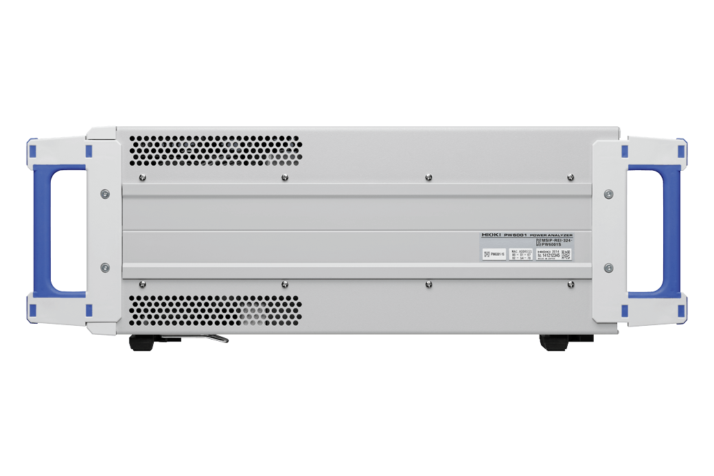
| Dimensions and mass | 430 mm (16.93 in)W × 177 mm (6.97 in)H × 450 mm (17.72 in)D, 14 kg (49.4 oz) (PW6001-16) | |||||
| Included accessories | Instruction Manual ×1, Power cord ×1, D-sub connector × 1 (PW6001-1x only) | |||||
Direct Current Input (1)
To connect to the Hioki ME15W (12 pin) terminal
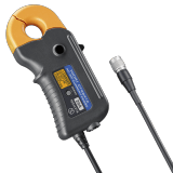
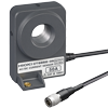
Up to 200 A (High precision) (8)
To connect to the Probe1 input terminal (Hioki ME15W terminal)
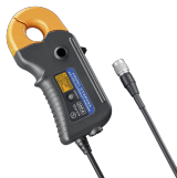
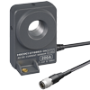
Up to 500 A (High precision) (5)
To connect to the Probe1 input terminal (HIOKI ME15W terminal)

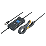
Up to 2000 A (High precision) (4)
To connect to the Probe1 input terminal (Hioki ME15W terminal)
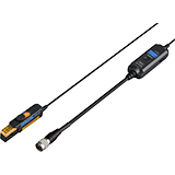
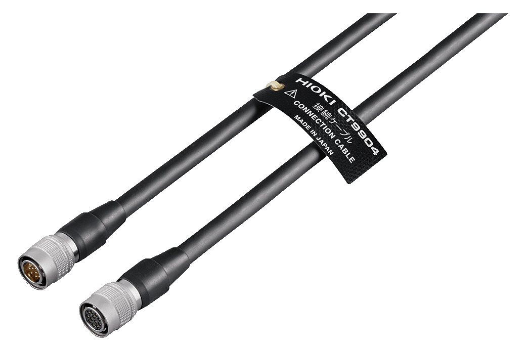
PL23 (10 pin) - ME15W (12 pin) conversion (1)
When using a PL23 terminal sensor without “-05” in the model number, Conversion Cable CT9900 must be used to connect to ME15W terminal.
When using the CT6865 and CT6846 (without “-05”), connection via the CT9900 and manual settings are required on the main device.
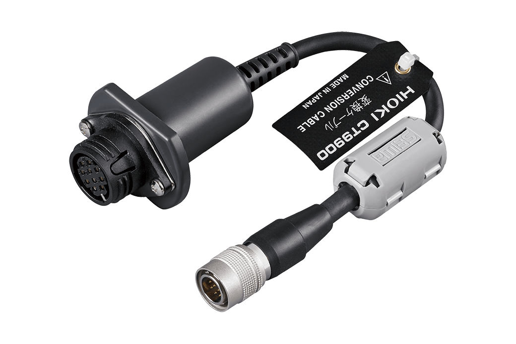
Convert PL23 (10-pin) terminal to ME15W (12-pin) terminal
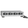
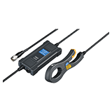
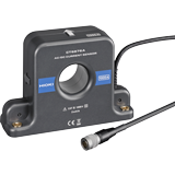
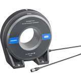
Up to 8000 A (High precision) (2)
Aggregate and measure large currents in multi-cable circuits
Use multiple AC/DC Current Sensor CT6877A units with the Sensor Unit CT9557 to measure currents of up to 8000 A in multi-cable circuits. Requires 1 connection cable to connect the PW6001/PW3390 to the CT9557.
ME15W (12 pin) terminal to ME15W (12 pin) terminal, 1 m (3.28 ft) length (for connecting CT9557 total output to PW6001 or PW3390 only)
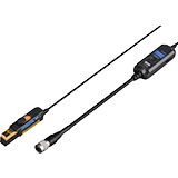
Up to 5 A (High speed) (2)

Up to 30 A (High speed) (2)
Up to 500 A (High speed) (2)
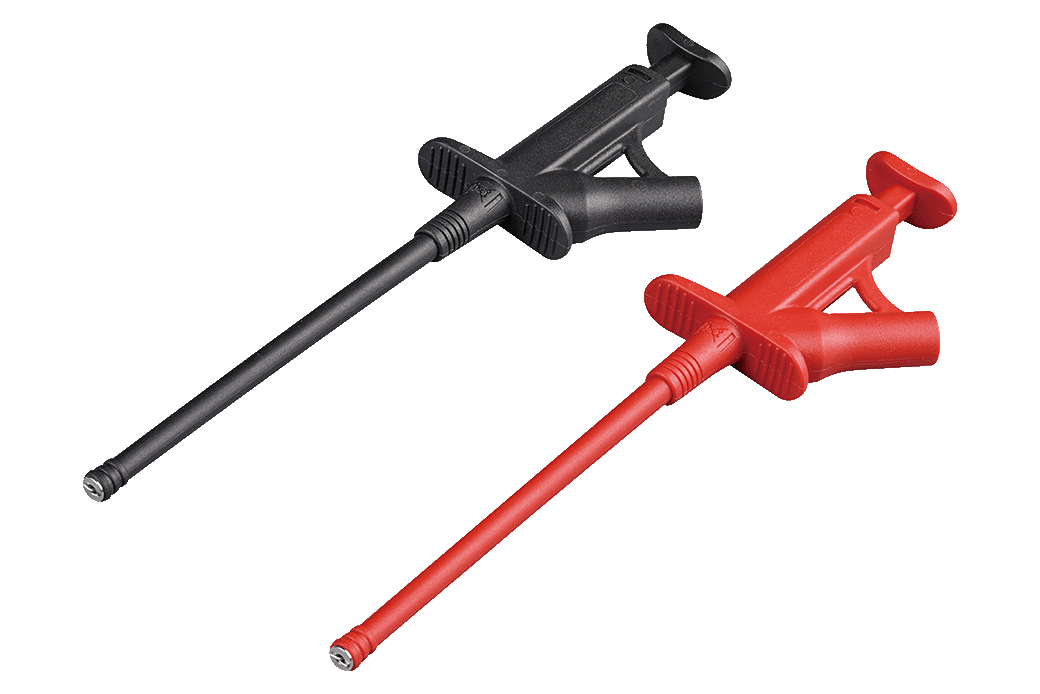
Voltage measurement (8)
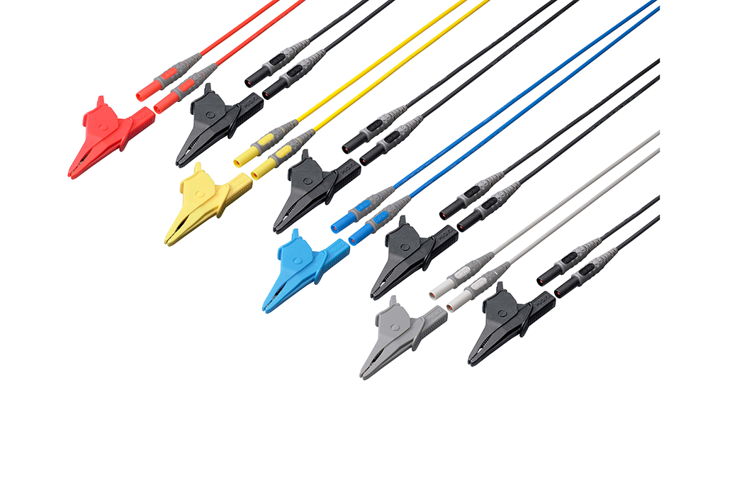
Red/ Yellow/ Blue/ Gray each 1, Black 4, 3m (9.84ft) length, Alligator clip ×8
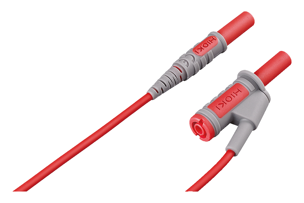
Banana branch-banana, Red: 1, 0.5 m (1.64 ft) length, for branching from the L9438s or L1000s, CAT IV 600 V, CAT III 1000 V
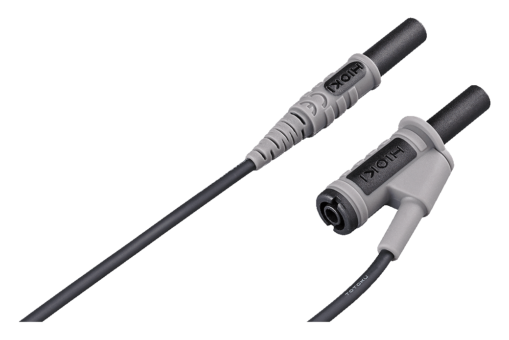
Banana branch-banana, Black: 1, 0.5 m (1.64 ft) length, for branching from the L9438s or L1000s, CAT IV 600 V, CAT III 1000 V
1.6 m
3.0 m
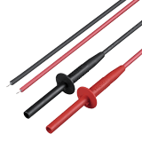
Attaches to the tip of the banana plug cable, Red/Black: 1 each, 185 mm (7.28 in.) length, CAT II 1000 V
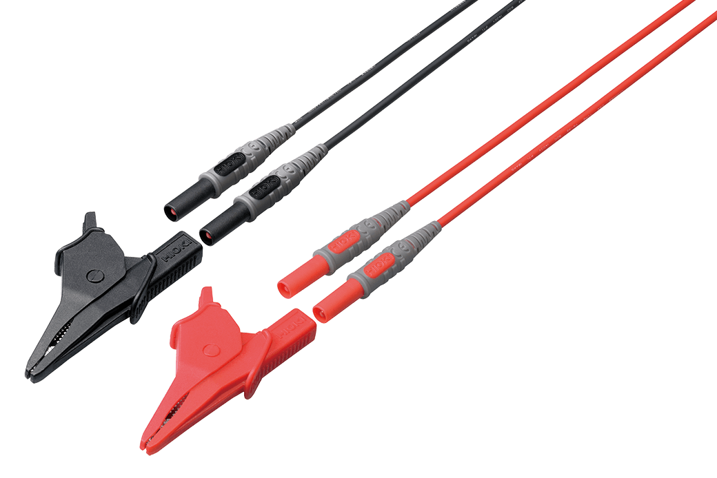
1000 V specifications, Black/ Red, 3 m (9.84 ft) length, Alligator clip ×2
Connection Options (9)
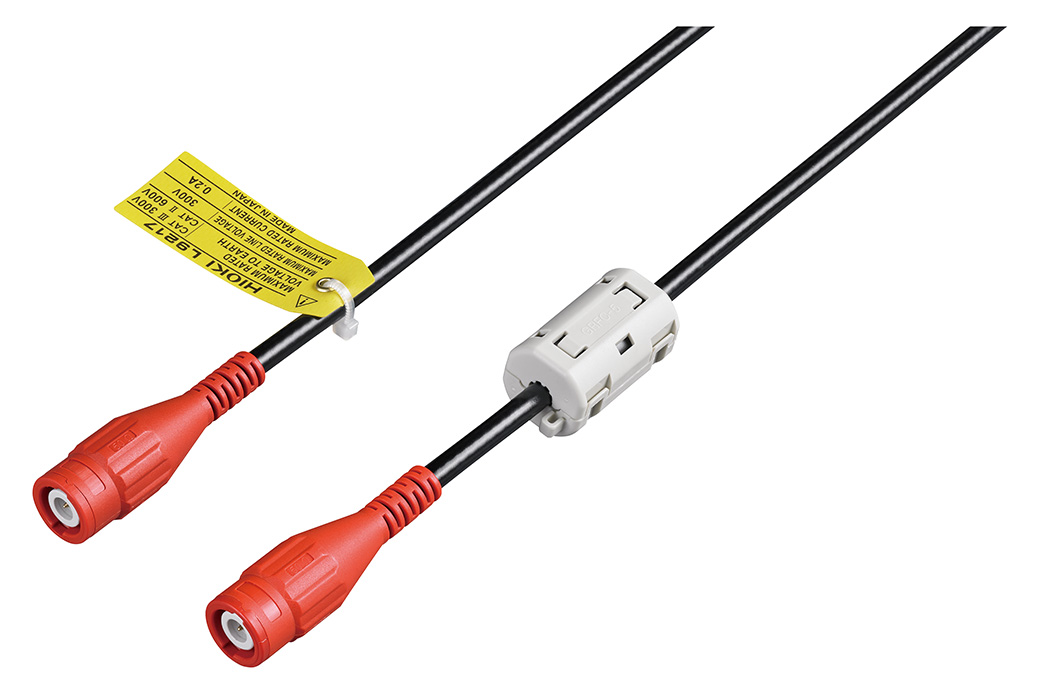
9444 for external control interface, L9217 for motor signal input
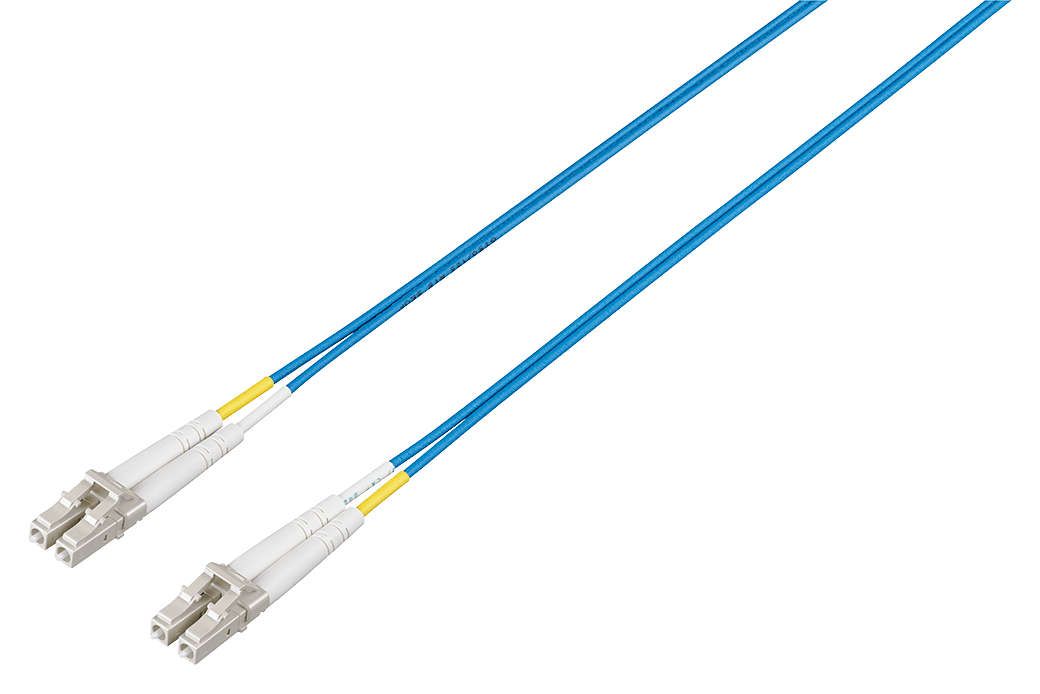
50/125 μm wavelength multimode fiber, 10 m (32.81 ft) length
Cord has insulated BNC connectors at both ends, 1.6 m (5.25 ft) length
Cord has insulated BNC connectors at both ends, 3.0 m (9.84 ft) length
Cord has insulated BNC connectors at both ends, 10 m (32.81 ft) length
2 m (6.56 ft) length
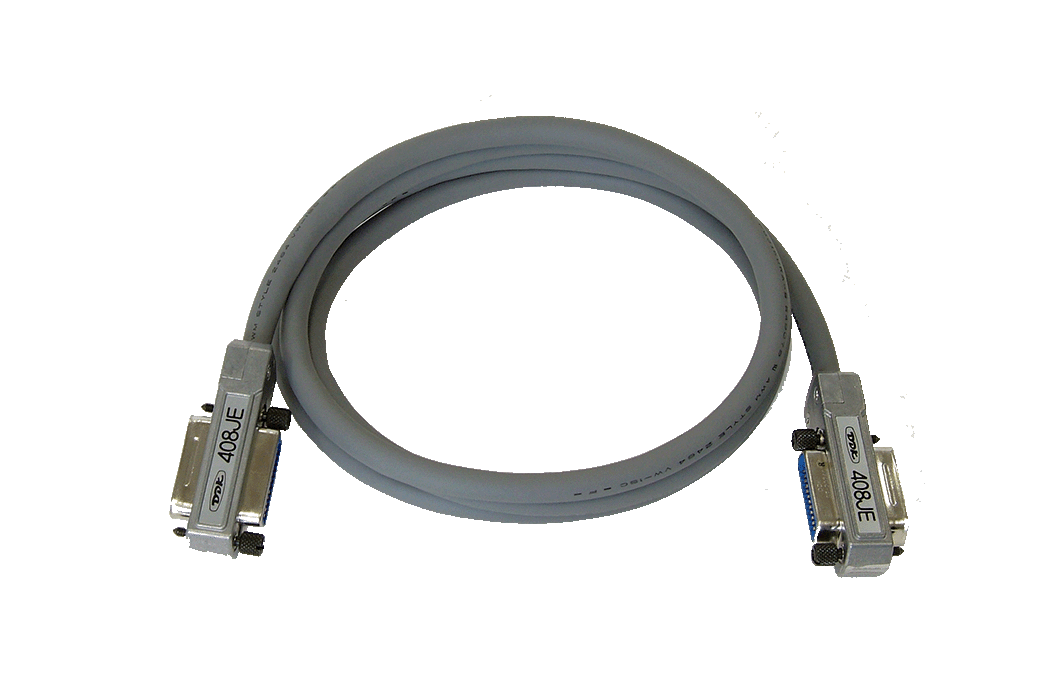
9 pin - 9 pin straight, 1.5 m (4.92 ft) length
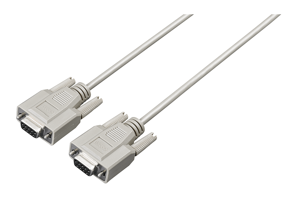
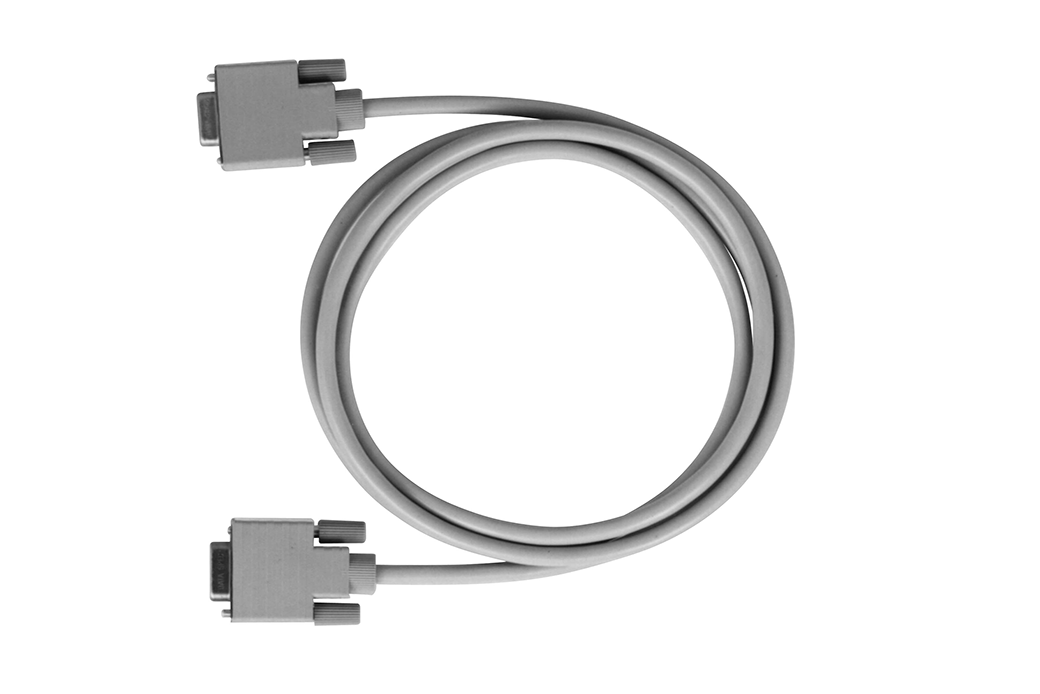
9 pin - 9 pin, cross, 1.8 m (5.91 ft) length
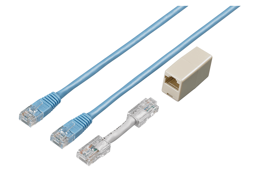
Straight Ethernet cable, supplied with straight-to-cross conversion adapter, 5 m (16.4 ft.)
Receiving side BNC (female), output banana (male) *Not compatible with older generation Memory Hicorders with banana input terminals
Other options (0)
The following made-to-order items are also available. Please contact your authorized Hioki distributor or reseller for more information.
• Carrying case (hard trunk, with casters)
• D/A output cable, D-sub 25-pin-BNC (male), 20 ch conversion
• Bluetooth® serial converter adapter cable 1 m (3.28 ft)
• Rackmount fittings (EIA, JIS)
• Optical connection cable, Max. 500 m (1640.55 ft) length
• PW9100 5 A rating version
• 2000A pull-through type sensor

-
Brochure: Measuring Instruments for the Battery Industry
 English
-
Brochure: POWER ANALYZER Series
English
-
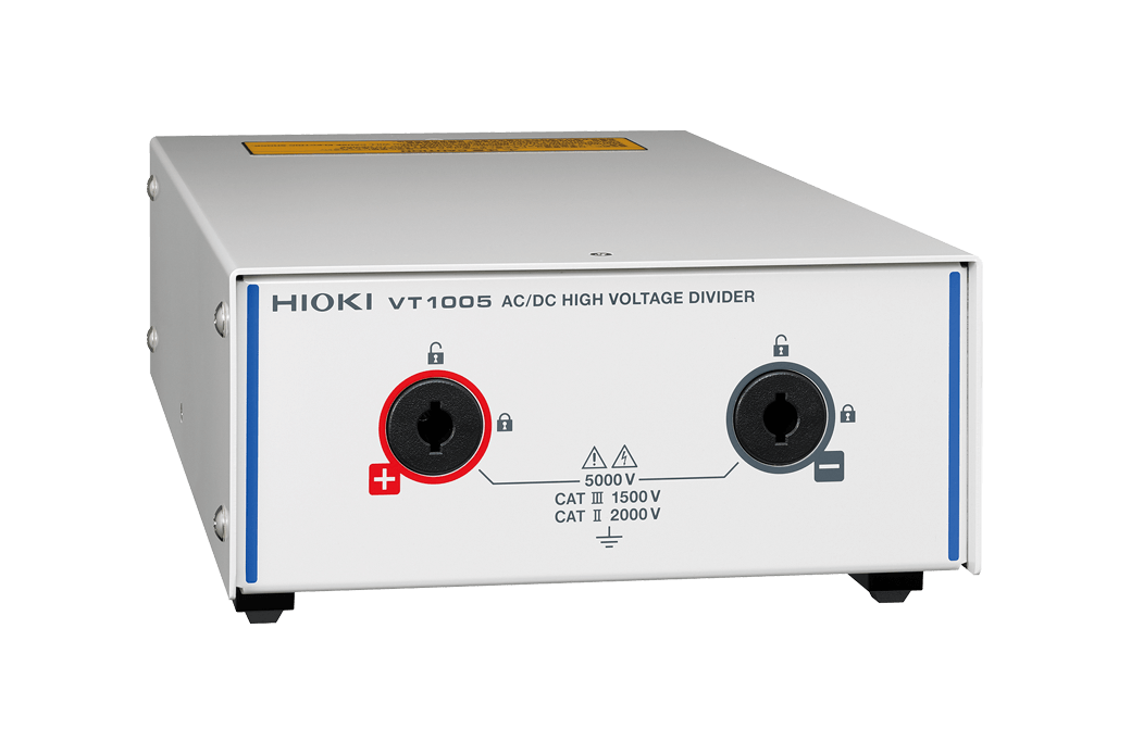
Brochure: AC/DC HIGH VOLTAGE DIVIDER VT1005
English
-
Brochure: POWER ANALYZER PW6001
English
-
GENNECT ONE SF4000
English
-
Flyer Catalog: LR8410 Link
English
-
Catalog: AC/DC CURRENT BOX PW9100
English
-
PW6001 Letter of Volatility
-
Effectiveness of Current Sensor Phase Shift When Evaluating the Efficiency of High-efficiency Motor Drives
-
Measurement of Loss in High-Frequency Reactors
-
High-precision Power Measurement of SiC Inverters
-
Current Measurement Methods that Deliver High Precision Power Analysis in the Field of Power Electronics
-
Identification of PMSM Motor Parameters with a Power Analyzer
-
Identification of PMSM Parameters with the Power Analyzer PW6001
-
High-precision, Wideband, Highly Stable Current Sensing Technology
-
Power Analyzer PW6001
-
Typical Values of Current Sensors’ Phase Characteristics
English
-
Typical Values of Current Sensors’ Phase Characteristics (when VT1005 is used)
English
-
Voltage, Current, and Power Measurement for Cycle-controlled Loads, Phase-controlled Loads, and Inverters
English
-
Electrical Measurements of Lithium-Ion Batteries
English
-
POWER ANALYZER PW6001-11, PW6001-12, PW6001-13, PW6001-14, PW6001-15, PW6001-16
Test Report
Japanese
English Ver.01 -
POWER ANALYZER PW6001-01, PW6001-02, PW6001-03, PW6001-04, PW6001-05, PW6001-06
Test Report
Japanese
English Ver.01 -
POWER ANALYZER PW6001-01, PW6001-02, PW6001-03, PW6001-04, PW6001-05, PW6001-06, PW6001-11, PW6001-12, PW6001-13, PW6001-14, PW6001-15, PW6001-16
Instruction Manual
English
Ver.10
-
POWER ANALYZER PW6001-01, PW6001-02, PW6001-03, PW6001-04, PW6001-05, PW6001-06, PW6001-11, PW6001-12, PW6001-13, PW6001-14, PW6001-15, PW6001-16
Quick Start Manual
French
Ver.06
-
POWER ANALYZER PW6001-01, PW6001-02, PW6001-03, PW6001-04, PW6001-05, PW6001-06, PW6001-11, PW6001-12, PW6001-13, PW6001-14, PW6001-15, PW6001-16
Instruction Manual
German
Ver.06
-
POWER ANALYZER PW6001-01, PW6001-02, PW6001-03, PW6001-04, PW6001-05, PW6001-06, PW6001-11, PW6001-12, PW6001-13, PW6001-14, PW6001-15, PW6001-16
Instruction Manual
Simplified Chinese
Ver.07
-
POWER ANALYZER PW6001-01, PW6001-02, PW6001-03, PW6001-04, PW6001-05, PW6001-06, PW6001-11, PW6001-12, PW6001-13, PW6001-14, PW6001-15, PW6001-16
Instruction Manual
Korean
Ver.05
-
POWER ANALYZER PW6001-01, PW6001-02, PW6001-03, PW6001-04, PW6001-05, PW6001-06, PW6001-11, PW6001-12, PW6001-13, PW6001-14, PW6001-15, PW6001-16
Communication Command Instruction Manual
English
Ver.07
-
POWER ANALYZER
PW6001-01, PW6001-02, PW6001-03, PW6001-04, PW6001-05, PW6001-06, PW6001-11, PW6001-12, PW6001-13, PW6001-14
-
POWER ANALYZER PW6001-01, PW6001-02, PW6001-03, PW6001-04, PW6001-05, PW6001-06, PW6001-11, PW6001-12, PW6001-13, PW6001-14, PW6001-15, PW6001-16
PW6001-01, PW6001-02, PW6001-03, PW6001-04, PW6001-05, PW6001-06, PW6001-11, PW6001-12, PW6001-13, PW6001-14, PW6001-15, PW6001-16
-
POWER ANALYZER
PW6001-01, PW6001-02, PW6001-03, PW6001-04, PW6001-05
- DC Current Superposition Testing of Coils Using a Power Analyzer
- DC Large Current and Power Conversion Efficiency Measurement of Plating System Power Supplies
- Winding the Secondary Coil (Detection Winding) when Measuring Iron Loss with the 2-Coil Method
- Loss Analysis of Reactors While in Operation
- Impedance Measurement of Reactors While in Operation
- Electric Angle Measurement of Motors