MEMORY HiCORDER MR6000
Highest Measurement Capabilities and Fastest Transfer Rate in History
The MR6000 overcomes all barriers to reach new ground and meet challenges that are yet to be seen. World class specifications, operability and design - Hioki’s newest memory recorder has been re-engineered from top to bottom, delivering unprecedented performance that will change how you look at waveform recording.
Key Features
- Work efficiently and intuitively using the MR6000’s large touch panel
- Captures momentary phenomena of each channel simultaneously with isolation measurement of up to 200 MS/s (when using the High Speed Analog Unit U8976)
- Enjoy a stress-free user experience thanks to dramatically faster saving of data
- Save data in real time while measurement continues.
Model No. (Order Code)
| MR6000 | Main unit only, input modules up to 8 units |
|---|---|
| MR6000-01 | Built-in real-time waveform calculation and other functionality |
Hioki MR6000 Memory HiCorder - Change the Way You Measure, Record and Analyze
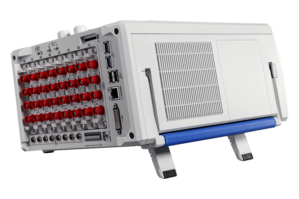
The MR6000’s 12.1-inch capacitive touch panel facilitates smooth, intuitive operation by allowing you to select settings simply by tapping them and to zoom in on waveforms with standard finger gestures.
Moreover, the Waveform Search function makes it easy to search large volumes of measurement data for the waveforms you wish to view.
The instrument can also automatically search all measured data for anomalous waveforms.
High-speed isolated measurement at 200 MS/s with simultaneous sampling
The High Speed Analog Unit U8976 boasts the highest sampling rate in its entire series, an order of magnitude faster than conventional models.
Enables the unit to perform isolated measurement at 200 MS/s, and each channel can be measured with simultaneous sampling.
Thanks to its overwhelmingly fast sampling speeds, the unit can accurately acquire changes in high-speed signals so that you can capture momentary phenomena.
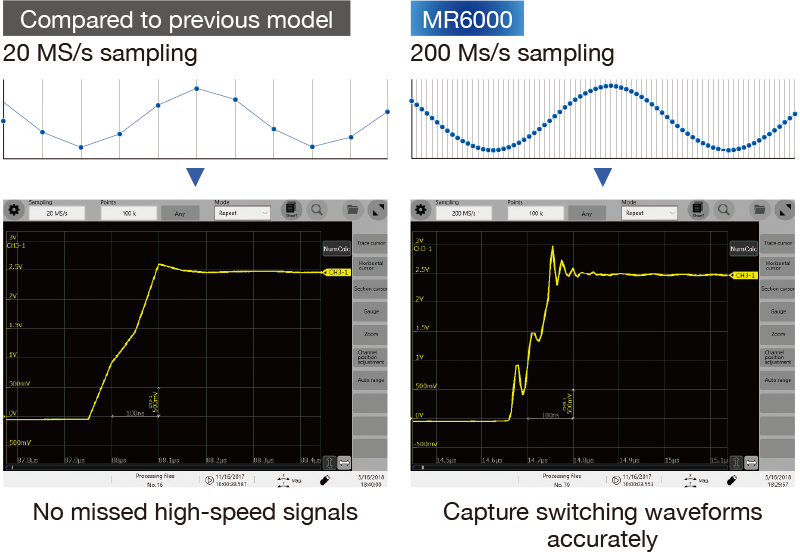
Frequency band and isolated performance that let you accurately capture high switching frequencies
The MR6000 provides isolated channels that can accept 400 V DC direct input while maintaining high-speed sampling at 200 MS/s, allowing it to accurately capture switching waveforms in evaluation testing of inverter and power supply designs that are required to deliver high levels of efficiency. Smooth operation lets you read trace values simply by flicking the flicking the cursor to the side.
Completely isolated input
Connections between analog input channels, and between the input channel and the main unit, are fully isolated. This means that, unlike an oscilloscope, measurements can be made without concern with negative effects from potential differences.
<< Optical isolation devices (HIGH SPEED ANALOG UNIT U8976)
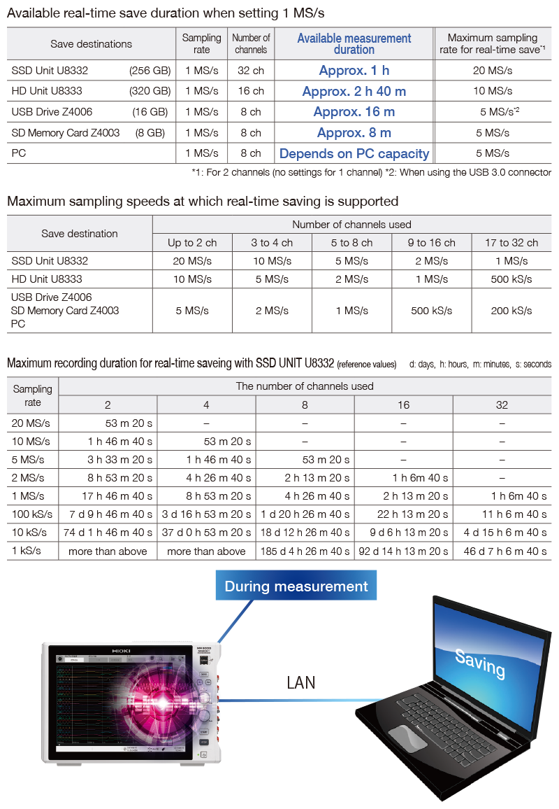
Save Time Reduced to 1/30th
Transferring very large amounts of data measured over a long period of time used to be very time-consuming.
The MR6000 features a brand new interface and faster internal processing, reducing the time required to save measurement data to media.
For example, a save operation that took 1 minute on the previous model now completes in 2 seconds. This saves you the trouble of waiting for data to be saved and improves work efficiency.
Long-term recording and high-speed sampling in multiple channels
The real-time save function controls the available measurement duration without relying on the capacity of the internal memory.
For long-term recording, we recommend a high-capacity SSD or HD unit. You can also use a more convenient USB memory stick or SD memory card.
All phenomena can be recorded at a high sampling rate over a long period of time.
《Saving data directly to your PC》
Transfer measurement data directly to your PC by using the FTP sending function together with the real-time save function. This makes it easier to observe data after the measuring process.
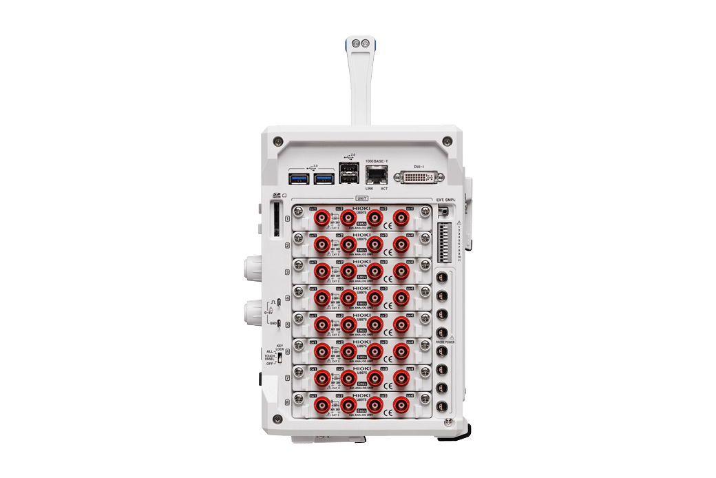
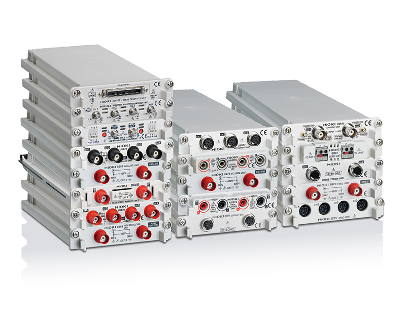
An Extensive Line of Units for Detecting a Wide Range of Phenomena
Combine multiple units to record a range of phenomena.
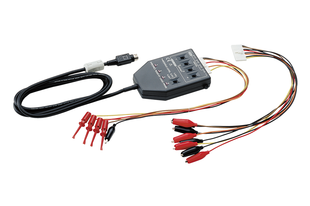
Use multiple logic units to measure relay ON/OFF signals or PLC (programmable logic controller) signals across up to 128 channels simultaneously.
You can also measure temperature by attaching a thermocouple to a temperature unit.
《Unit selection guide》
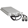
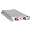
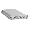
HIGH SPEED ANALOG UNIT U8976
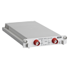
ANALOG UNIT 8966
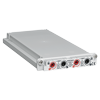
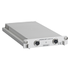
4CH ANALOG UNIT U8975
4CH ANALOG UNIT U8978
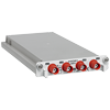
HIGH RESOLUTION UNIT 8968
DC/RMS UNIT 8972
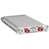
HIGH VOLTAGE UNIT U8974
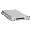
DIGITAL VOLTMETER UNIT MR8990
3CH CURRENT UNIT U8977
CURRENT UNIT 8971
TEMP UNIT 8967
STRAIN UNIT U8969
FREQ UNIT 8970
CHARGE UNIT U8979
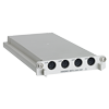
LOGIC UNIT 8973
ARBITRARY WAVEFORM GENERATOR UNIT U8793
WAVEFORM GENERATOR UNIT MR8790
PULSE GENERATOR UNIT MR8791
See the “Options” tab of the MR6000 webpage for more information about units.
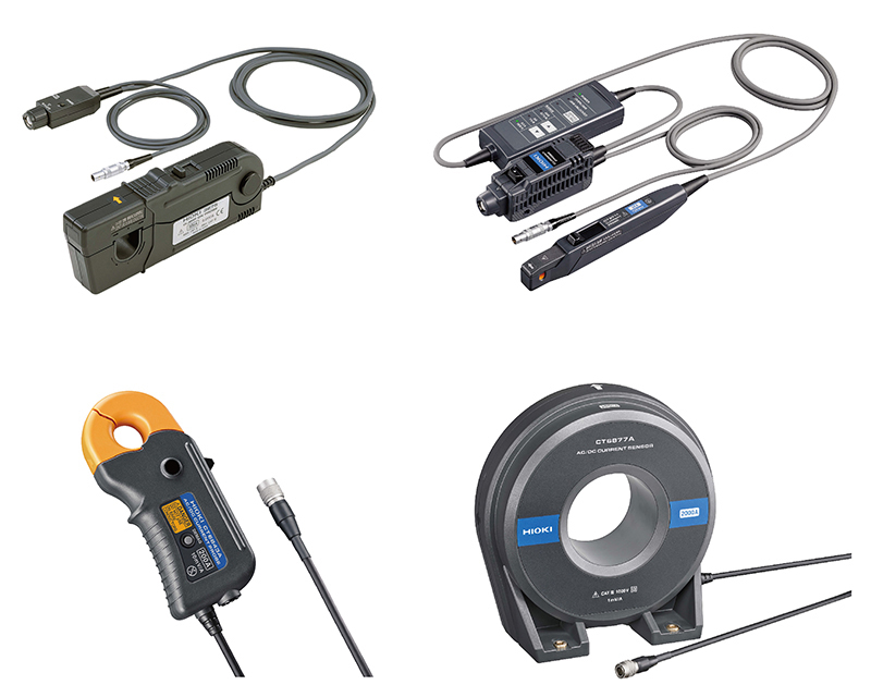
High-sensitivity, high-precision, broadband current probes and sensors
《Current probe》
Analyze minuscule current waveforms from low-power consumption devices in 100 μA resolution. Record device current consumption waveforms in high resolution over extended periods of time.
Additionally, the optional Probe Power Unit Z5021 can supply power to current probes from the MR6000.
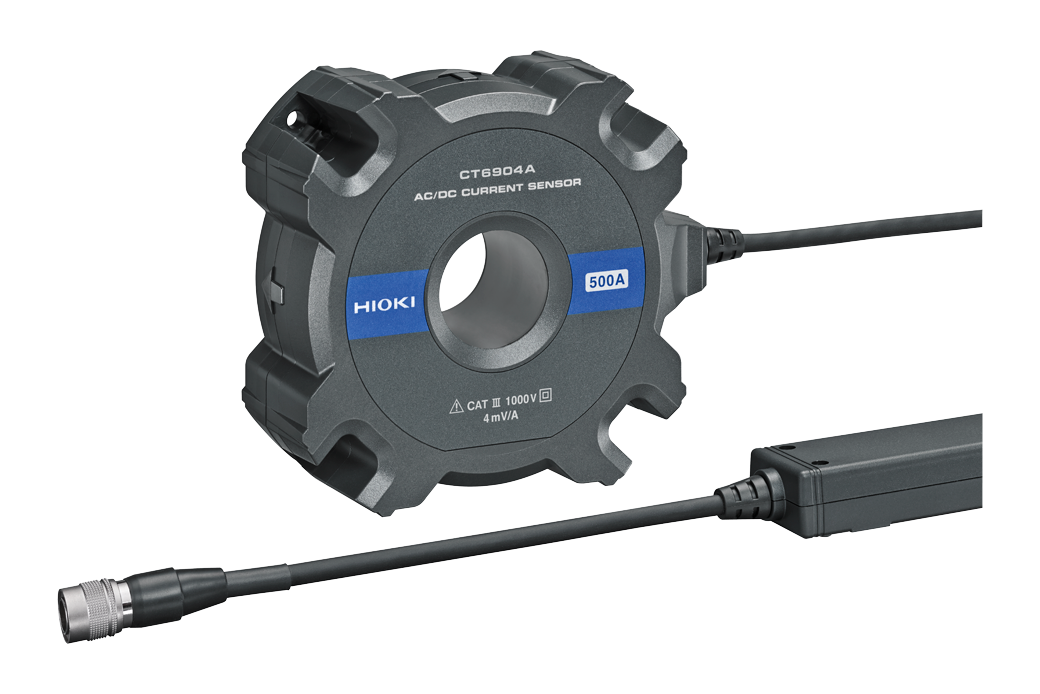
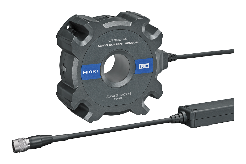
《Current sensor》
Clamp-type high-accuracy sensors deliver excellent temperature characteristics, allowing highly accurate measurements to be made even in the confined space of a vehicle’s engine compartment.
The 3ch Current Unit U8977 lets you connect current sensors directly, allowing the MR6000 to power them and scale readings automatically.
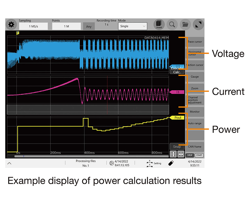
[Since Ver. 4.01] Power measurement
functionality
1. Display of voltage, current, and power trends
When measuring voltage and current after configuring power calculation settings, the instrument automatically performs waveform calculations and displays power values. In addition, it can display calculation results after measurement if you configure the power calculation settings.
2. Cycle-by-cycle calculations
The instrument performs calculation processing for each cycle, defined as the interval from one zero-cross point to the next zero-cross point, based on the waveform chosen as the reference channel.
3. Simple settings screen
A dedicated screen makes it easy to configure settings for power calculations, including wiring method and voltage and current channels.
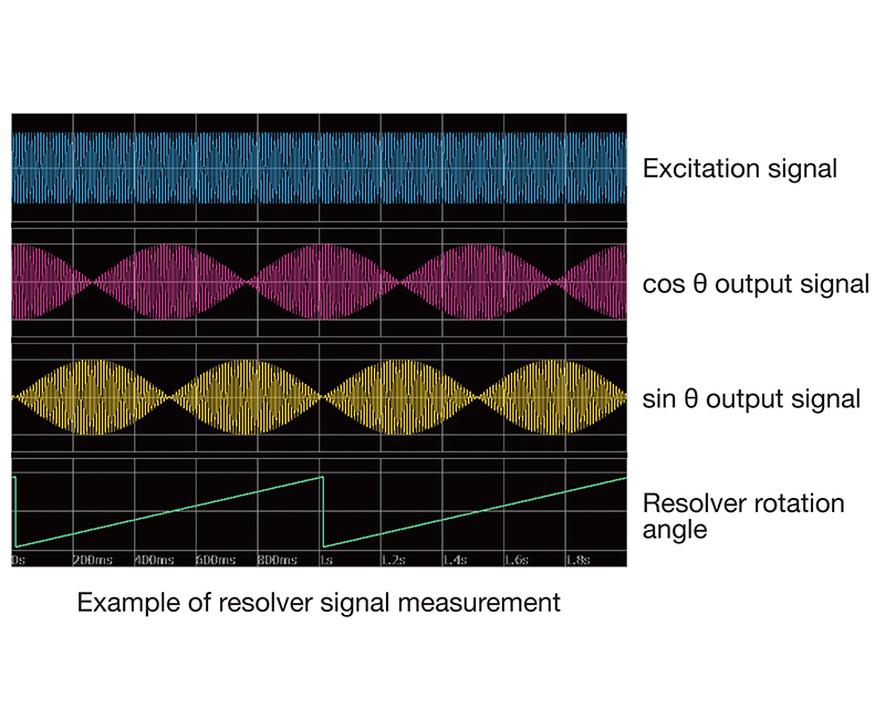
[Since Ver. 4.01] Rotation angle measurement functionality
1. Measurement of resolver rotation angle
Using the waveform calculation function, the instrument acquires three channels of data (resolver excitation signal, cos θ, and sin θ) and generates a trend display for the motor’s rotation angle.
2. Measurement of rotary encoder rotation angle
Using the waveform calculation function, the instrument acquires the A, B, and Z pulse signals from the rotary encoder and generates a trend display for the motor’s rotation angle.
*Only incremental method is available. Absolute method is not available.
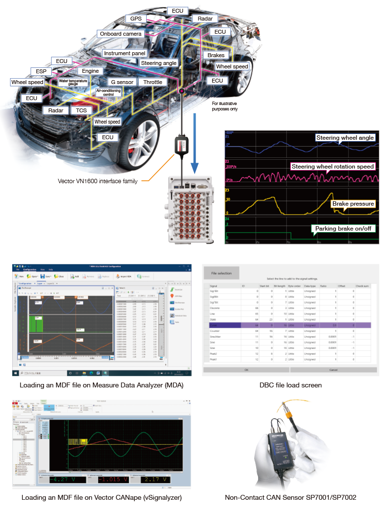
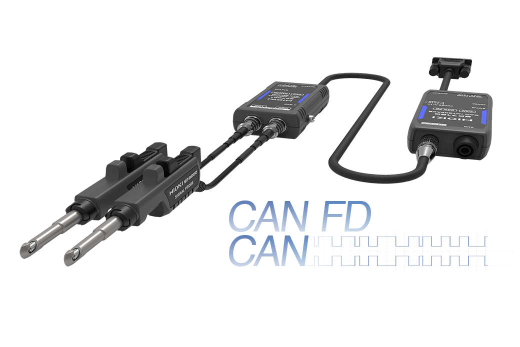
[Since Ver. 3.5] CAN/CAN FD, LIN Measurement
CAN buses and LIN buses carry not only control information, but also sensor information required by the ECU for control purposes. Analog values for sensor input signal quantities such as voltage, strain, temperature, flow rate, RPM, torque, vehicle speed, and vibration can be measured at the same time as these signals.
《Capture all data on the CAN and LIN bus during measurement》
The MR6000 captures all frame data on the CAN or CAN FD bus and LIN bus during the set recording time. After measurement, you can specify the signals you wish to check and display them on the screen.
《Load to waveform viewers compatibled with MDF format》
Analog, logic, CAN, and LIN data measured using the MR6000 are saved in MDF (Measurement Data Format) and can be loaded by any waveform viewer that supports MDF.
《Load DBC and LDF files with the MR6000》
Set the definitions by loading DBC and LDF files on the MR6000. A PC is not required.
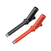
《Hioki offers CAN signal acquisition sensors》
• No modification of vehicle cables
Acquire signals simply by pinching the cables with the probe
• No effect on the CAN bus or vehicle ECUs
Non-contact sensing technology
• Accurate, reliable signal capture
Ideal for use in development and evaluation applications
For more information about SP7001 and SP7002, please check here.
Calculate measurement data during measurement (Real-time waveform processing) *MR6000-01 feature
The MR6000-01 further features powerful technology designed for robust real-time waveform processing. This function performs the four arithmetic operations (addition, subtraction, multiplication, and division), differentiation calculations, or integration calculations during the measuring process, letting you use check the calculated results via waveforms while measuring or apply triggers during monitoring. Results can be further processed after measurement and saved.
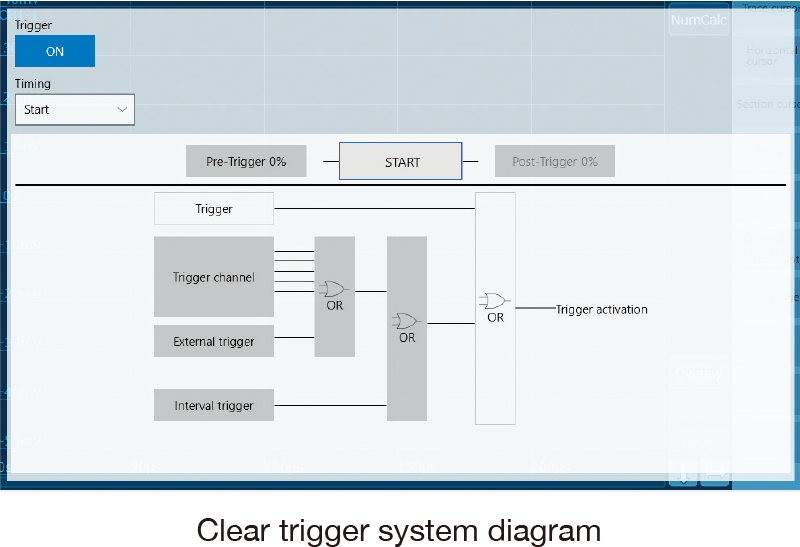
Triggers that detect targeted events
Set triggers on any channel to record data whenever an event occurs. Triggers can be set for all channels.
Level trigger : Compares to one voltage value.
Window trigger : Compares to two voltage values.
Voltage drop trigger : Detects voltage drops in commercial power lines.
Period trigger : Monitors periods.
Glitch trigger : Detects anomalies in pulses.
Pattern trigger : Compares when the logic signal is ON/OFF.
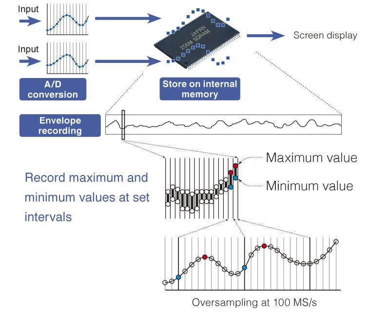
Observe fluctuations for extended periods of time without reducing the sampling rate (Envelope function)
The system uses the envelope measurement method to record maximum and minimum values at set intervals while performing oversampling at 100 MS/s. The internal memory has a capacity of 1 G-words, which ensures that the measuring process can continue for a long time without any data loss.
Save data in real time while measuring.
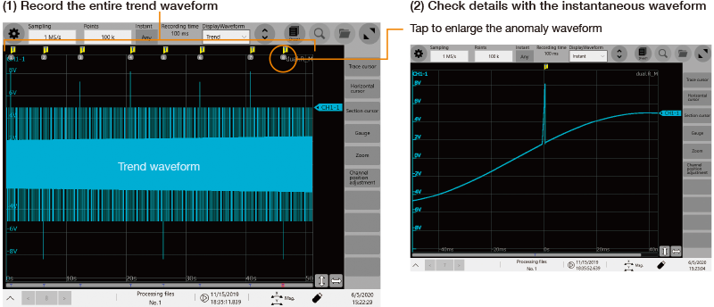
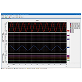
Measure anomalies during extended testing with high-speed sampling (Dual sampling function)
In vibration testing, it's necessary to record comprehensive test data for several hours. At the same time, it’s necessary to capture areas of the waveform where anomalies occur with high-speed sampling for analysis once measurement is complete.
The dual sampling function is useful in such situations.
(1) Record the entire trend waveform
Use the envelope function to record comprehensive test data for several hours.
(2) Check details with the instantaneous waveform
Anomalies occurring during the test will be captured with high-speed sampling based on triggers that have been set up in advance. By tapping on a trigger mark’s number, you can display the instantaneous waveform for the anomaly that occurred at that waveform area.
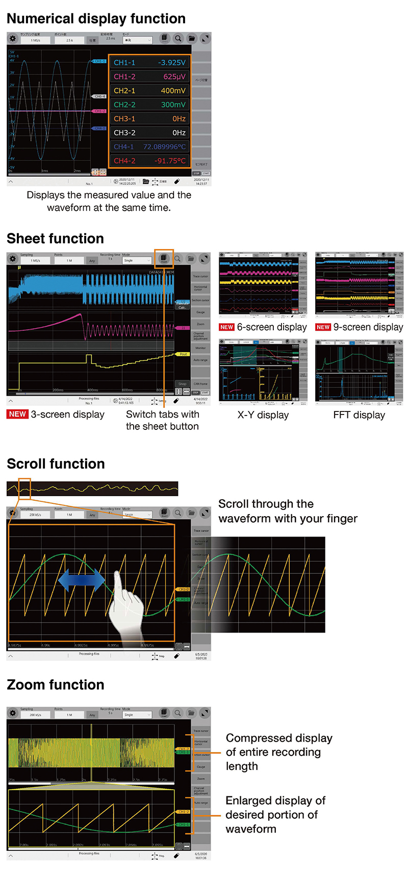
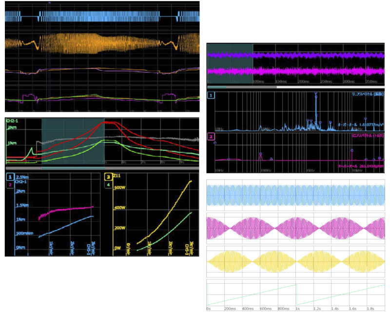
Display Functions
《Numerical display function》
This function is effective for checking the status before and during measurement.
《Sheet function (display group)》
Switch among 16 sheets to analyze the waveform from various perspectives.
《Scroll function》
You can use the scroll function to check the waveform as if viewing it on paper.
《Zoom function》
The zoom function allows you to display all measurement waveforms on a single screen, in the manner of an oscilloscope, and to view desired locations in greater detail.
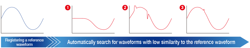
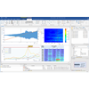
Easily search for waveforms in huge volumes of measurement data
The Memory HiCorder Concierge function automatically calculates the characteristics of a reference waveform set by the customer and then searches all measured data while identifying waveforms that do not resemble the reference waveform as anomalous waveforms. This drastically reduces the amount of time required to search for anomalies by eliminating the need to scroll through measured waveforms and checking them visually.
Additionally, this function is ideal for situations where it is difficult to set the right triggers before measuring because the nature of potential anomalies cannot be predicted.
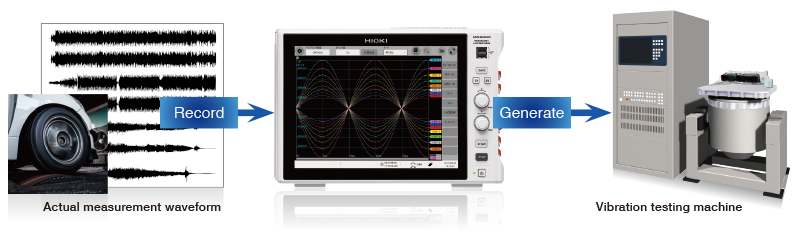
Achieving the dual role of generation and recording with a single unit
The arbitrary waveform generation function and waveform measurement function are realized by one Memory HiCoder.
For more information about ARBITRARY WAVEFORM GENERATOR UNIT U8793, please check here.
Numerical calculation function
By performing numerical calculations on measured waveforms, you can perform analyses using numerical parameters. Not only analog channels and logic channels, but also results of the real-time waveform calculation function can be used in this calculations.
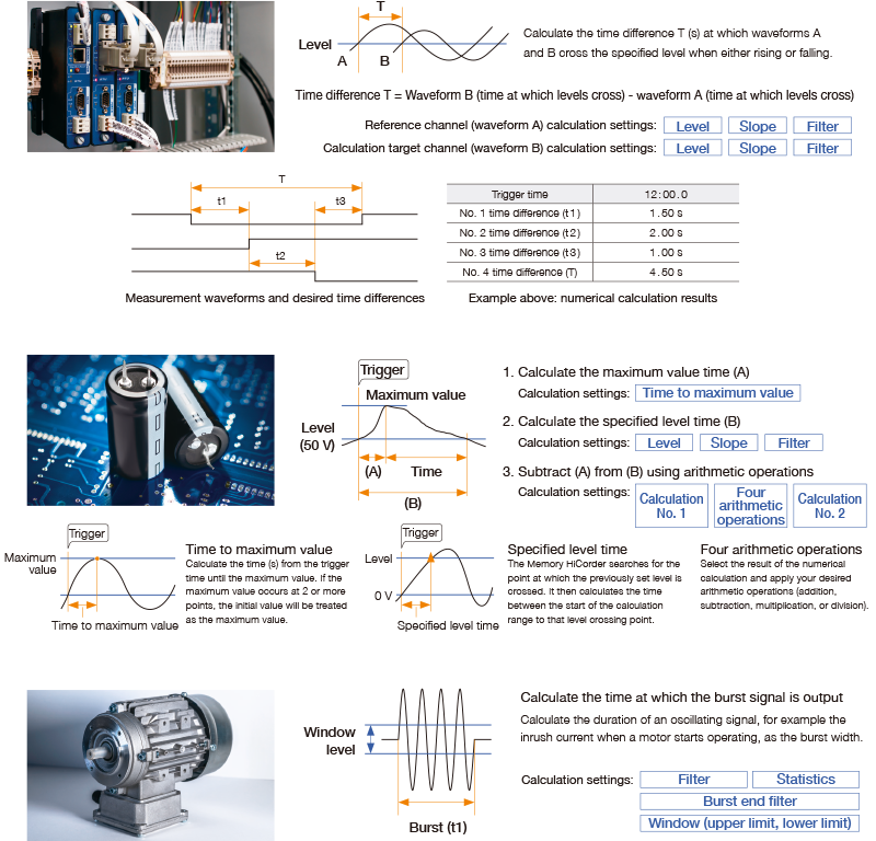
《Calculating switching times measured using logic channels (t1, t2, t3, T) 》
You can calculate time differences by applying numerical calculations to signals measured using logic channels.
《Calculating the time that elapses until a reading falls from the maximum value to a defined level (50 V) after a capacitor is charged during capacitor charge/discharge testing》
You can calculate the desired value by calculating the time at which the maximum value occurs and the time at which the specified level occurs using numerical calculations and then performing your desired arithmetic operations.
《Calculating the motor inrush starting current time (t1) 》
You can derive the desired time by calculating the burst width using numerical calculations.
Applications
《Power Fluctuation Measurement》
Please check the MR6000 catalog.
《Motor Torque and Vibration Measurement》
Please check the MR6000 catalog.
《Measurement of Dynamic Motor Characteristics》
Please check the MR6000 catalog.
《Calculate a Resolver’s Angle of Rotation》
https://www.hioki.com/global/learning/applications/detail/id_113479
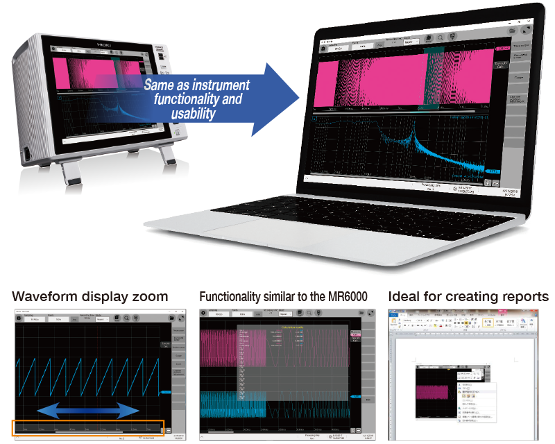
PC Software 《MR6000 Viewer》
Load data measured with the MR6000/MR6000-01 onto a PC to display waveforms and perform calculations. Utilize functionality similar to that provided by the MR6000 on a PC, including numerical calculations, waveform processing, and FFT calculations. (Some restrictions apply.)
Supported models: MR6000, MR8847A, MR8827, MR8740, MR8741
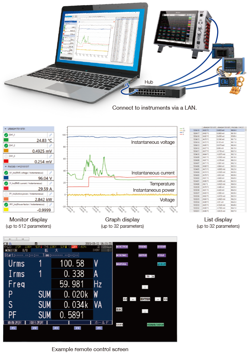
PC Software 《GENNECT One》
GENNECT One lets you display and save data in real time on a PC during measurement. It also serves as a useful tool in measurement applications that include other instruments.
《Simultaneous, real-time observation》
GENNECT One lets you display data from multiple instruments together and in real time in list or graph form.
《LAN remote control function》
Change instrument settings and control operation, for example to start or stop measurement.
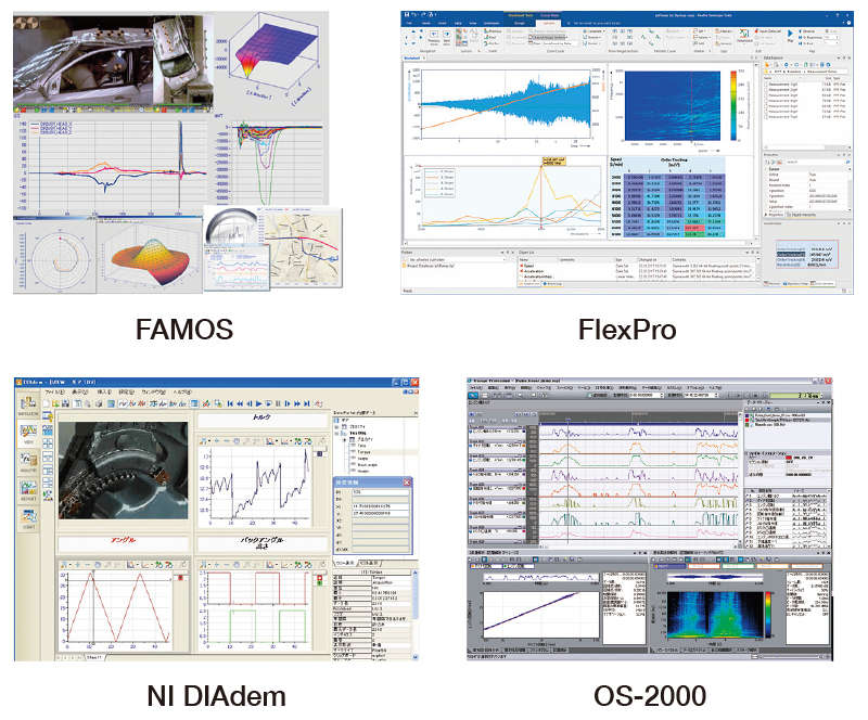
Commercially available software
《FlexPro》
· High-speed search and processing of large volumes of data
· Share analysis templates inside your company
《NI DIAdem》
· Functionality ranging from searching and loading of data to analyzing and creating of reports
· Dialog-based interface
《FAMOS》
· More than 400 calculation processing variables
· Easy report creation functionality
Design accolades
《2018 iF Design Award》
The MR6000 received an iF Design Award from Industrie Forum Design Hannover, an international organization that promotes design.
《2018 Japan Manual Contest》
The MR6000 and MR6000-01 Memory HiCorder’s Quick Start Manual received an Excellence Award in the industry category of the Japan Manual Contest.
《2018 Good Design Award》
One judge observed, “The MR6000’s design has been tweaked so that the product, which was originally designed for use in maintenance settings, can also be used in the development of inverter and power conditioner technologies to improve the energy efficiency of these continually evolving devices. Refined to detect the effects of minuscule changes, the product is praiseworthy for balancing research-oriented functionality and user friendliness while significantly boosting measurement precision. Its features include isolated channels, a readily portable design, accommodation of extended measurement time as evident in design touches like the ergonomic angle of its monitor and use of a touch panel, and an interface that allows users to view multiple phenomena at once. Through all of these, one can see the designer’s thoughtfulness towards both the maintenance and R&D engineer.

Basic specifications
| MR6000 | MR6000-01 | |||||
| Additional function | N/A | Real-time waveform calculation, Digital Filter calculation. | ||||
| Number of input units | Max. 8 units | |||||
| Number of channels | Max. 32 analog channels (when using the U8975), or 128 logic channels (when using the 8973) | |||||
| Measurement ranges (20 div full-scale) | 10 mV to 400 V f.s., 12 ranges (when using the U8976), Resolution : 1/1600 of range 4 V to 200 V f.s., 6 ranges (when using the U8975), Resolution : 1/32000 of range |
|||||
| Max. allowable input | 1000 V DC / 700 V AC (when using the U8974), 200 V DC (when using the U8975), 400 V DC (when using the U8976) | |||||
| Frequency characteristics | DC to 30 MHz (when using the U8976), DC to 2 MHz (when using the U8975) | |||||
| Max. sampling rate | 200 MS/s, all channnels simultaneously (when using the U8976) External sampling: 10 MS/s |
|||||
| Recording methods | Normal: Normal waveform recording Envelope: Record maximum and minimum values every fixed period |
|||||
| Storage memory capacity | 1 G-words | |||||
| Removable storage | SD memory card ×1, USB memory ×7, SSD/HDD (built in the main unit) ×1 FTP transmission (to LAN-connected computer) *Use only Storage Media sold by HIOKI. |
|||||
| Display | 12.1 inch XGA-TFT color LCD (1024 × 768 dots) | |||||
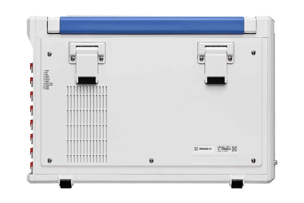
| External interfaces | LAN, USB, SD, SATA, Monitor output | |||||
| Power supply | 100 to 240 V AC (50/60 Hz) (300 VA max.) | |||||
| Dimensions and mass | 353 mm (13.9 in)W × 235 mm (9.25 in)H × 154.8 mm (6.09 in)D, 6.5 kg (229.3 oz) (main unit only) | |||||
| Included accessories | Power cord ×1, Quick start manual ×1, Precautions conserning use ×1, Application disk (CD-R) ×1, Instruction manual (CD-R, detail and calculation) ×1 , Blank panel (for blank slots only) | |||||
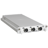
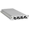
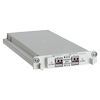
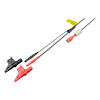
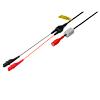
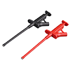
Input modules (15)
Input cords not included. Please purchase separately.
When using 9709 with CURRENT UNIT 8971, a total of 7 current probes can be used.
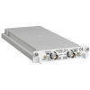


Output modules (3)
Output cords not included. Please purchase separately.
Factory-installed option A (1)
*Must specify when ordering
*Power can be supplied to up to 8 current sensors, including the current sensors connected to the CURRENT UNIT 8971.
Specified upon order of the MR6000, power max. 4 × CT6710 series, or max. 8 × other probes
Factory-installed option B (1)
*Must specify when ordering
Must be specified at time of order; internal drive, 256 GB
Factory-installed option C (1)
*Must specify when ordering
Must be specified at time of order; internal drive, 320 GB
Storage media (3)
Precaution
*Use only the storage media sold by Hioki. Compatibility and performance are not guaranteed for storage media made by other manufacturers. You may be unable to read from or save data to such media.
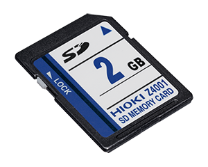
2 GB capacity
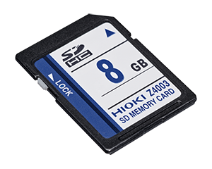
8 GB capacity
16 GB, long-life, high-reliability SLC flash memory
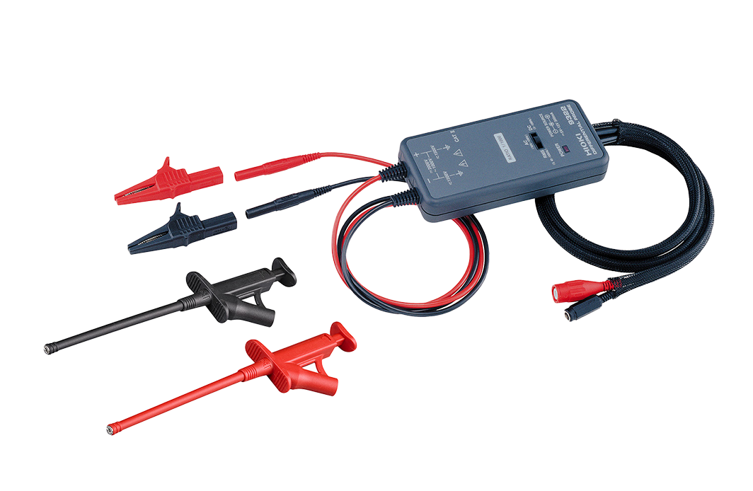
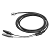
External sampling measurement (2)
Max. rated voltage to earth: 33 Vrms AC or 70 V DC, SMB to alligator clip, 1.5 m (4.92 ft) length
Max. rated voltage to earth: 33 Vrms AC or 70 V DC, SMB to BNC terminal, 1.5 m (4.92 ft) length
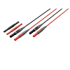
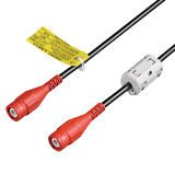
Input Cord (A) (4)
Voltage is limited to the specifications of the input modules in use.

• Flexible φ 4.1 mm (0.16 in) thin dia.
• Cable allowing for up to 600 V input
• 1.8 m (5.91 ft) length
Red/black set attaches to the ends of the Connection Cord L9790

Red/black set attaches to the ends of the Connection Cord L9790

Red/black set attaches to the ends of the Connection Cord L9790
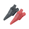
Input Cord (B) (3)
Voltage is limited to the specifications of the input modules in use.
•φ 5.0 mm (0.20 in) dia
•Cable allows for up to 600 V input
•1.8 m (5.91 ft) length
•Includes detachable large alligator clips
•φ 5.0 mm (0.20 in) dia.
•Cable allows for up to 300 V input
•1.7 m (5.58 ft) length
•Small alligator clip
Attaches to the tip of the banana plug cable, Red/Black: 1 each, 185 mm (7.28 in.) length, CAT II 1000 V
Input Cord (C) (2)
Voltage is limited to the specifications of the input modules in use.
Input Cord (D) (2)
Voltage to ground is within this product's specifications. Separate power source is also required.
Custom cable for P9000 (0)
Please contact your authorized Hioki distributor or reseller.
(1) Bus powered USB cable
(2) USB(A)- Micro B cable
(3) 3-prong cable
Input Cord (E) (2)
Voltage to ground is within this product's specifications. Separate power source is also required.
100 to 240V AC
Input Cord (F) (6)
Voltage input via banana terminals limited by the voltage specifications of the respective input unit.
Expands the length of L4930/4940, 1.5 m (4.92 ft) length
Attaches to the tip of the L4930/4940, CAT IV 600 V, CAT III 1000 V
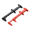
Attaches to the tip of the L4930/4940, CAT III 600 V
Attaches to the tip of the L4930/4940, CAT III 1000 V

Banana plug - banana plug, 1.5 m (4.92 ft) length, red/black each 1
Attaches to the tip of the banana plug cable, Red/Black: 1 each, 185 mm (7.28 in.) length, CAT II 1000 V
Input Cord (G) (1)
For the MR8990. Voltage is limited to the specifications of the input modules in use.

70 cm (2.30ft) length, detachable large alligator clips or needle tips are bundled, CAT IV 600V, CAT III 1000V
Non-contact voltage measuring (0)
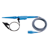
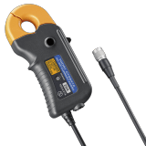
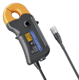
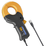
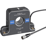
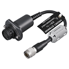
Non-contact CAN Sensor (1)
Other options for input (3)
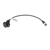
Cord has insulated BNC connectors at both ends, 1.6 m (5.25 ft) length
Metal BNC to clip, 1.5 m (4.92 ft) length
Receiving side banana (female), output BNC (male)
Temperature sensor (0)
THERMOCOUPLE
*For reference only. Please purchase locally.
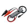
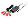
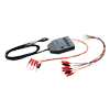
Logic signal measurement (3)
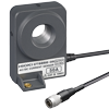
Up to 200 A (High precision) (6)
Separate power supply (CT955x) is required in order to use a high-precision current sensor.
Only sensors with ME15W (12-pin) terminals can be connected to the CT955x.
The separately available CONVERSION CABLE CT9900 is required in order to use a sensor with a PL23 (10-pin) terminal.
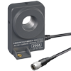
Up to 1000 A (High precision) (7)
Separate power supply (CT955x) is required in order to use a high-precision current sensor.
Only sensors with ME15W (12-pin) terminals can be connected to the CT955x.
The separately available CONVERSION CABLE CT9900 is required in order to use a sensor with a PL23 (10-pin) terminal.

PL23 (10-pin) - ME15W (12-pin) conversion (1)
Convert PL23 (10-pin) terminal to ME15W (12-pin) terminal
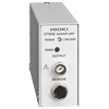
POWER SUPPLY for Current Sensors (4)
Separate power supply (CT955x) is required in order to use a high-precision current sensor.
Only sensors with ME15W (12-pin) terminals (-05 type) can be connected to the CT955x
The separately available CONVERSION CABLE CT9900 is required in order to use a sensor with a PL23 (10-pin) terminal.

Cord has insulated BNC connectors at both ends, 1.6 m (5.25 ft) length
Directly connectable with the Current Sensor (2)
Up to 4 CURRENT UNITS 8971 can be connected to the MEMORY HiCORDER main unit, and up to 8 current sensors can be used, including those connected to the PROBE POWER UNIT Z5021.
The separately available CONVERSION CABLE CT9901 is required in order to use a high-precision current sensor equipped with a ME15W (12-pin) terminal (-05 type) with the CURRENT UNIT 8971.
While the CT955x is not required in order to use a sensor equipped with a PL23 (10-pin) terminal with the 8971, the CONVERSION CABLE 9318 (which comes with the 8971) is required for that setup.
To connect the CT6841-6846, CT6865/63/62, 9709, 9272-10 to the 8971/40/51, 38 cm (14.96 in) length
Precautions for connecting high-precision current sensors (0)
- High-precision current sensor (ME15W) + CT9901 +
9318 → CURRENT UNIT 8971
- High-precision current sensor (ME15W) + CT955x + BNC cable → except CURRENT UNIT 8971
- High-precision current sensor (PL23) + 9318 → CURRENT UNIT 8971
- High-precision current sensor (PL23) + CT9900 + CT955x + BNC cable → except CURRENT UNIT 8971
*The 9318 comes with the CURRENT UNIT 8971.
10 mA class to 500 A (High speed) (4)
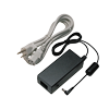
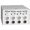
Power supply (2)
Leak Current (2)
For commercial power lines, 50/60 Hz
100 V to 240 V AC
PC Software (4)

Straight Ethernet cable, supplied with straight-to-cross conversion adapter, 5 m (16.4 ft.)
Case (1)
For the MR6000, hard trunk type, for storing options
-
Brochure: CURRENT SENSOR, PROBE Series
 English
-
Brochure: MEMORY HiCORDER MR6000
English
-
GENNECT ONE SF4000
English
-
Preview Catalog: MR6000 Viewer
English
-
Brochure: Motor Measurement Applications
English
-
MEMORY HiCORDER MR6000, MR6000-01
Test Report
Japanese
English Ver.00 -
MEMORY HiCORDER MR6000, MR6000-01
Instruction Manual
English
Ver.08
-
MEMORY HiCORDER MR6000,MR6000-01
Quick Start Manual
English
Ver.06
-
MEMORY HiCORDER MR6000, MR6000-01
Quick Start Manual
Simplified Chinese
Ver.05
-
MEMORY HiCORDER MR6000, MR6000-01
Instruction Manual
Simplified Chinese
Ver.06
-
MEMORY HiCORDER MR6000-01
MR6000-01 Dedicated Functions
English
Ver.01
-
MEMORY HiCORDER MR6000-01
MR6000-01 Dedicated Functions
Simplified Chinese
Ver.00
- Unlock Insights by Using Hioki’s Memory HiCorder MR6000 for Motor Bench Analysis
- Versatile Instrument for Various UPS Operational Tests
- ISO 21782: EV Propulsion Component Test Specifications and Measuring Instruments
- Connectable Products of the Non-Contact CAN Sensor SP7001/SP7002
- Current Consumption Measurement for Low Energy Devices
- Calculate a Resolver’s Angle of Rotation
- Operational Testing of Engines Used in Outboard Motors
- Record Encoder Pulse Output to Verify Motor Operation
- Measure the Touch Sensitivity of Push Switches
- Data Acquisition and Assessment in Railway Car Trial Runs (Train)
- Motor Rotation Measurement
- Recording and Monitoring of Conveyor Speeds
- Operational Testing of Multiple-circuit Protective Relays