Zero-voltage Measurement of Electric Vehicles
The fully battery-powered electric vehicle (BEV) needs inspections and service just like the combustion-engine vehicle. Nevertheless, unlike the combustion-engine vehicle, BEVs are equipped with high-voltage (HV) components, such as HV batteries and inverters, which can cause electric shock if handled carelessly. So, to make sure the safety of the technician, the HV system needs to be safely shut down before inspection or repair work.
In this application note, you will learn about zero-voltage measurement, which is an important measurement for inspecting and servicing BEVs. Zero-voltage measurement is an electrical test that verifies that the HV system of the vehicle has been shut down. While maintaining or inspecting a BEV, a technician conducts mechanical tests as well as electrical tests, such as an insulation test and an equipotential test. Zero-voltage measurement is necessary to guarantee the safety and reliability of these electrical tests.
Note: For details on the procedure of how to conduct zero-voltage measurement on an electric vehicle, please check with the vehicle. manufacturer
Measurement purpose
The purpose of this measurement is to prevent electric shock and make sure that the vehicle is shut down. In this measurement, we verify that the measurement points where high voltage may be generated is at zero volts (0 V). The zero-voltage test is carried out between the HV battery and the inverter. It is performed three times: once before disconnecting the HV cable, once after disconnecting the HV cable, and once before reconnecting the HV cable. The measurement can be performed with a multimeter.
| Measurement timing | Purpose |
|---|---|
| 1. Before disconnecting the HV cable between the HV battery and the inverter | To measure the zero-voltage on surfaces that are likely to be touched when unplugging the HV connector |
| 2. After disconnecting the HV cable between the HV battery and the inverter | To safely repair or inspect the BEV, ensure that the vehicle is free of hazardous voltage |
| 3. Before reconnecting the HV cable between the HV battery and the inverter | To check that the HV cable can be connected safely after the BEV has been repaired or inspected |
Measurement flow
Preparation before measurement: Shutting down the vehicle's HV system
Be sure to shut down*1 the vehicle's HV system by disconnecting the service plug or switch before carrying out any electrical tests or measurements.
- *1: The removal of high-voltage components is hazardous work. Ensure that qualified personnel specified by the laws and regulations with professional training perform the work. For details, please follow the operation manual of each vehicle manufacturer.
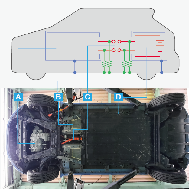
For reference, the locations of the measurements are labeled as follows:
- A: Inverter, motor, etc.
- B: Chassis
- C: HV cable
- D: HV batteries
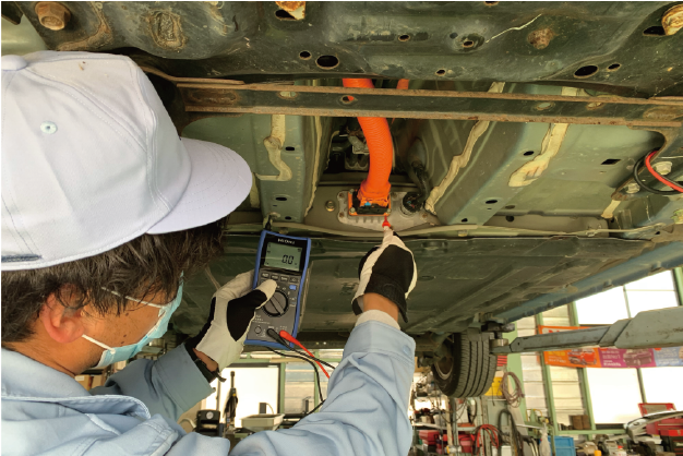
Measurement 1: Before disconnecting the HV cable after vehicle shutdown
After shutting down the vehicle's HV system, zero-measurement is performed on surfaces that are likely to be touched when disconnecting the HV cable connector. Table 1 shows examples of the measurement points.
Table 1: Examples of the measurement points.
| Measurement point | Multimeter terminal (+) | Multimeter terminal (−) |
|---|---|---|
| HV battery side | Places likely to be touched when disconnecting the HV connector | Chassis ground (GND) |
Measurement 2: After disconnecting the HV cable
After disconnecting the HV cable, wait for at least 10 minutes for the HV system to discharge, then conduct the zero-voltage measurement again.
As shown in Table 2, measurements are done at the HV battery-side connector and the inverter-side connector. To avoid serious accidents, it is necessary to wait for a certain period of time. Take note that the discharge time may vary, so make sure to check with the vehicle manufacturer.
Table 2: Examples of the measurement points.
| Measurement point | Multimeter terminal (+) | Multimeter terminal (−) |
|---|---|---|
| HV battery side | Positive terminal of the connector (+) | Chassis ground (GND) |
| Negative terminal of the connector (−) | Chassis ground (GND) | |
| Positive terminal of the connector (+) | Negative terminal of the connector (−) | |
| Inverter side | Positive terminal of the connector (+) | Chassis ground (GND) |
| Negative terminal of the connector (−) | Chassis ground (GND) | |
| Positive terminal of the connector (+) | Negative terminal of the connector (−) |
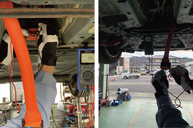 Zero-voltage measurement on the HV battery side (left figure) and inverter side (right figure)
Measurement 3: Before reconnecting the HV cable after the inspection
After completing the repair or inspection, do a zero-voltage measurement on the inverter and battery sides before safely reconnecting the HV system. Table 3 shows the measurement points for the HV battery side and inverter side. Since there is a diode on the inverter side, it is necessary to switch the polarity, so the test is performed twice.
Table 3: Examples of the measurement points.
| Measurement point | Multimeter terminal (+) | Multimeter terminal (−) |
|---|---|---|
| HV battery side | Positive terminal of the connector (+) | Chassis ground (GND) |
| Negative terminal of the connector (−) | Chassis ground (GND) | |
| Inverter side | Positive terminal of the connector (+) | Chassis ground (GND) |
| Negative terminal of the connector (−) | Chassis ground (GND) | |
| Chassis ground (GND) | Positive terminal of the connector (+) | |
| Chassis ground (GND) | Negative terminal of the connector (−) |
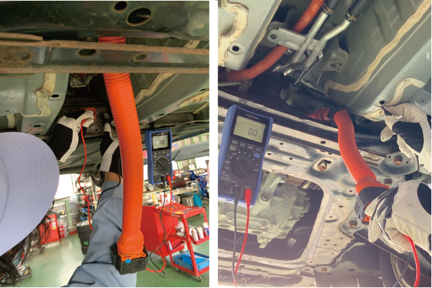 Zero-voltage measurement on the HV battery side (left figure) and inverter side (right figure)
For safer and more efficient measurements
Next, we will take a look at Hioki's digital multimeter DT4261, including its features and why it is a good choice for performing zero-voltage measurements.
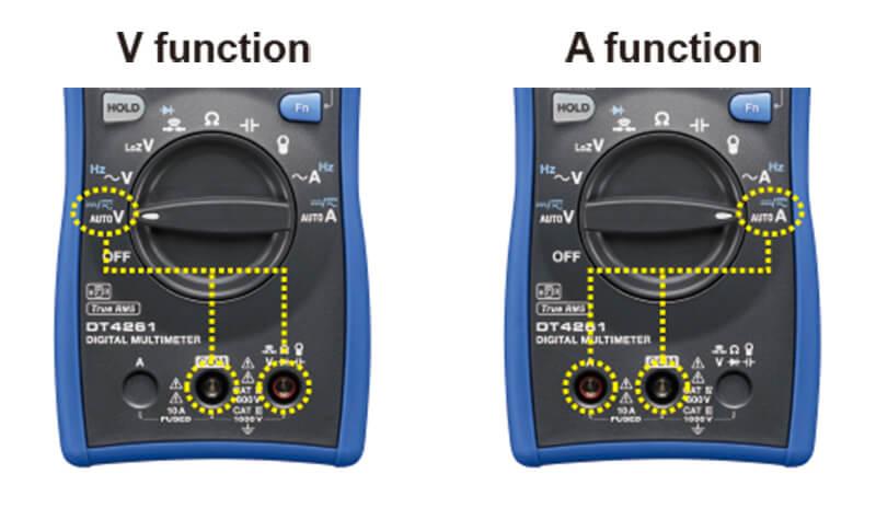
- 1.The DT4261’s terminal shutters make it physically impossible to insert the wrong test lead when measuring. The terminal shutters are linked to the instrument’s rotary switch so that it can prevent an honest mistake in connection that can cause extreme injury by causing voltage overload to the DMM.
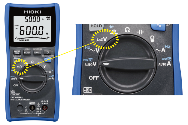
- 2. The LoZ (low input impedance) mode eliminates the effects of ghost voltages induced by the stray capacitance of the measurement target and the high input impedance of the multimeter. This enables you to get accurate reading.
- 3.For better handling of the instrument:
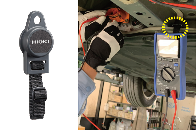
Conduct the measurement with both hands while the magnetic strap Z5020 holds the DT4261 to the vehicle.
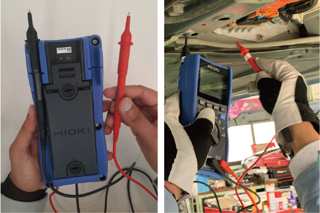
Attach one of the test leads into the holder for greater convenience in handling the instrument.
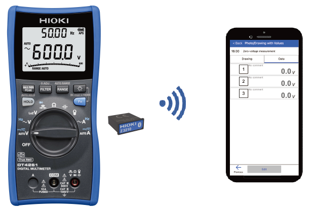
- 4. Installing the Wireless Adapter Z3210 to the DT4261 allows Bluetooth® connections. By connecting the instrument to the mobile app GENNECT Cross, you can digitize and manage your measurement data. Say goodbye to pen and paper for recording your inspection data.
Finally
Zero-voltage measurement is crucial for technician safety during electric vehicle inspections and servicing. The DT4261, a Bluetooth® compatible digital multimeter, is indispensable for EV maintenance thanks to its safety and convenient features. For further information on the instrument and the measurements utilized to ensure BEV safety, please do not hesitate to visit the DT4261 page or contact us. At HIOKI, we provide solutions for the safe and effective maintenance of BEVs.