What is Partial Discharge?
Overview
The IEC 60034-18-41 definition of partial discharge: Electric discharge that only partially bridges the insulation between electrical conductors. These small, localized electrical discharges are more likely when the internal insulation is deteriorating and can significantly impact the equipment's reliability. For example, in motors and generators operating under high voltage, partial discharge can arise in the insulation. Over time, repeated occurrences can degrade this insulation, ultimately leading to equipment failure. Consequently, detecting partial discharge during manufacturing is crucial to ensure only high-quality, well-insulated products are released, and periodic inspections for insulation weaknesses are equally important. This article will delve into the world of electrical discharge, with a particular emphasis on understanding and detecting partial discharge.
Various discharge phenomena
Fig. 1 shows a voltage applied across and air-insulated electrode. Depending on the applied voltage, this leads to a series of electrical events as shown in fig. 2. Initially (from 0 to point A), as the voltage climbs, the current increases smoothly in response. However, in the next phase (from A to B), the current plateaus because the number of charge carriers (electrons and ions) doesn't change. If we push the voltage higher still, beyond point B, a process called "impact ionization" kicks in. This is where electrons gain enough energy to collide with air molecules, knocking out more electrons. The region between B and C is characterized by intermittent discharges like partial discharge and corona discharge, but the insulation is not yet fully compromised. Corona discharge is a localized phenomenon occurring near electrodes where the electric field is very strong; it often produces sound and a faint glow. Once the applied voltage surpasses point C, we see a spark discharge, indicating that the insulation has broken down, allowing a continuous flow of current.
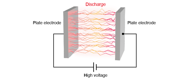
Fig. 1 Discharge between air-insulated electrode
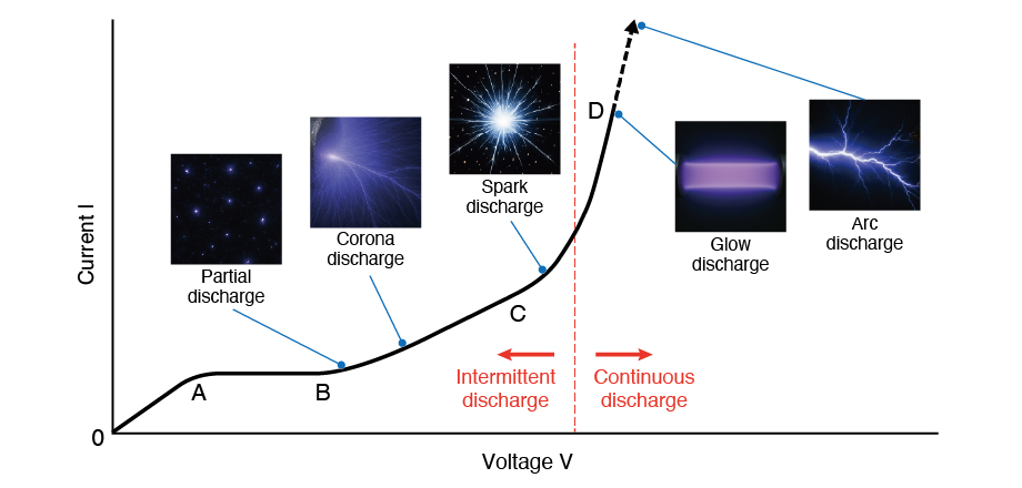
Fig. 2 Voltage-Current Characteristics of Partial Discharge and Other Discharge Types
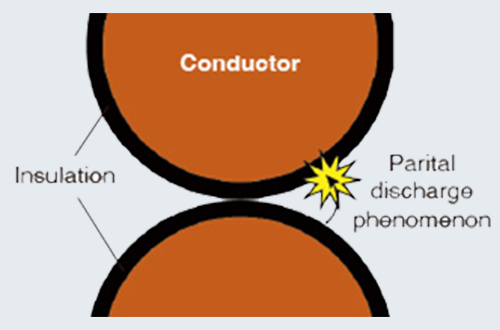
Partial discharge: Partial discharge occurring in a crater-like void (gas-filled)
Corona discharge: Partial discharge concentrated around electrodes with strong local electric fields is termed corona discharge, and it's accompanied by sound and a faint light.
Spark discharge: Increasing the voltage further can cause a brief discharge phenomenon that bridges the gap between the electrodes. If corona discharge conditions aren’t met, a spark discharge can occur abruptly.
Glow discharge, Arc discharge: Discharge phenomenon in which an excessively high voltage breaks down the insulation and forms a continuous conductive path between the electrodes
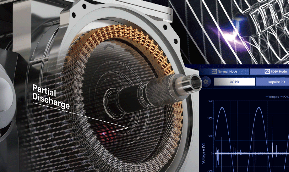
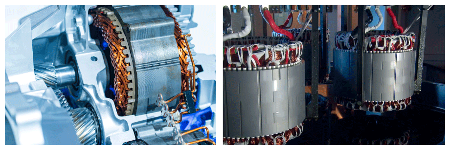
Discharge within a motor stator
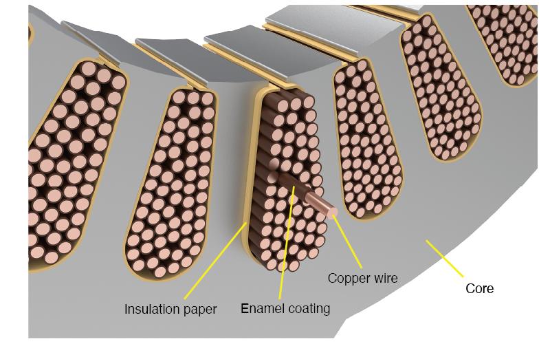
The stator of an electric motor consists of a core and a coil. The core is electrically insulated from the coil with insulation paper. The insulation needs to withstand a specified voltage without partial discharge. The insulation needs to withstand a specified voltage without partial discharge.
Above this voltage, the stator may show partial discharge as shown in fig. 3.
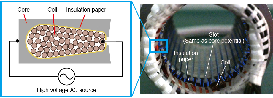
Fig. 3 Good sample - Discharge voltage 1.8 kVrms
On the other hand, partial discharge occurs below the specified voltage, if the stator is faulty. For example, fig 4 shows a case where the insulation paper is misaligned, at 1.3 kVrms, corona discharge was observed.
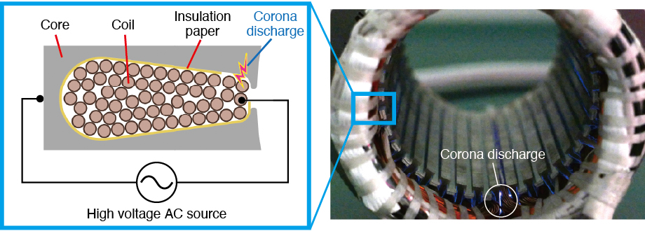
Fig. 4 Misaligned insulation paper condition – Discharge voltage 1.3 kVrms
Deterioration of Insulators due to partial discharge
Let's consider the problems caused by partial discharge using enameled wire (magnet wire). Enameled wire is widely used in motors, transformers, inductors, loudspeakers, etc. Enameled wire is a copper wire that is coated with enamel as an insulator as shown in fig. 5. Within the enamel coating, voids, or air pockets, can form.
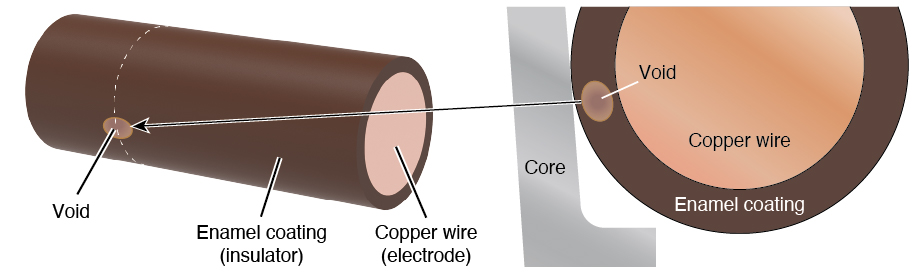
Fig. 5 Enameled wire with a void
When a high voltage is applied to the copper wire, the electric field concentrates in these void areas because they have a lower dielectric constant. This causes partial discharge to occur within the voids, leading to the dissolution of the insulator and chemical reactions, which degrades the insulation as shown in fig. 6. If this degradation progresses, it eventually results in insulation breakdown as shown in fig. 7. The purpose of partial discharge testing is to detect the state of partial discharge early, before insulation breakdown occurs.
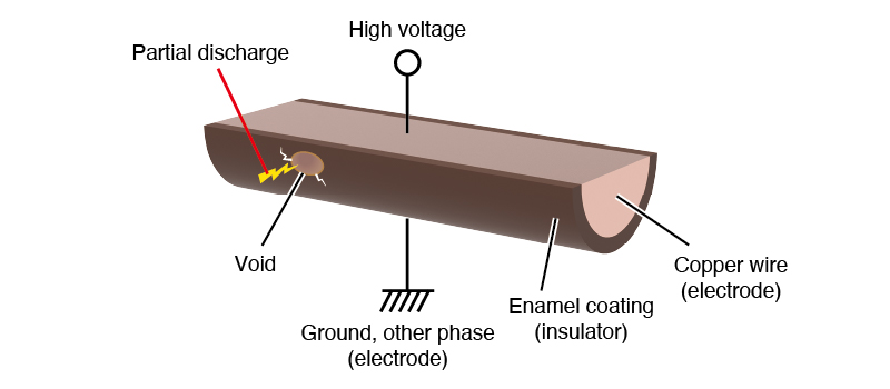
Fig. 6 Partial discharges inside a void
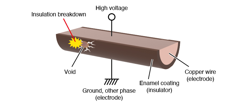
Fig. 7 Insulation breakdown
Introduction of Partial Discharge Testers
While inverter-driven motor systems offer improved efficiency, their higher switching voltages can lead to surge voltages that are more than twice the switching voltage of conventional motor drives. This elevated voltage increases the likelihood of partial discharge, and as a result, quickly deteriorate insulation. Therefore, partial discharge testing is essential for guaranteeing the long-term reliability of these motors.
For comprehensive tests of modern high-efficiency motors test engineers need to perform two types of partial discharge tests: 1) AC PD test and 2) Surge PD test.
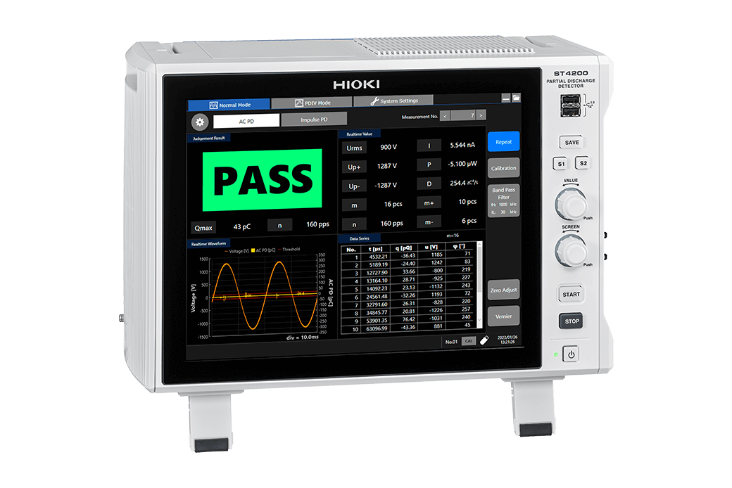
The AC PD test detects phase-to-phase and phase-to-core PD. In the AD PD test the tester applies 50 or 60 Hz voltages and measures the resulting current. Fig. 8 shows a typical AC PD measurement.
The Surge PD test detects turn-to-turn partial discharge by simulating inverter surges. This evaluation assesses the surge endurance between turns within the same phase. The tester applies a voltage impulse to the motor and detects surge current as shown in fig. 9.
When using HIOKI’s ST4200 Partial Discharge Detector, test engineers can perform both AC PD tests and Surge PD tests with a single instrument.
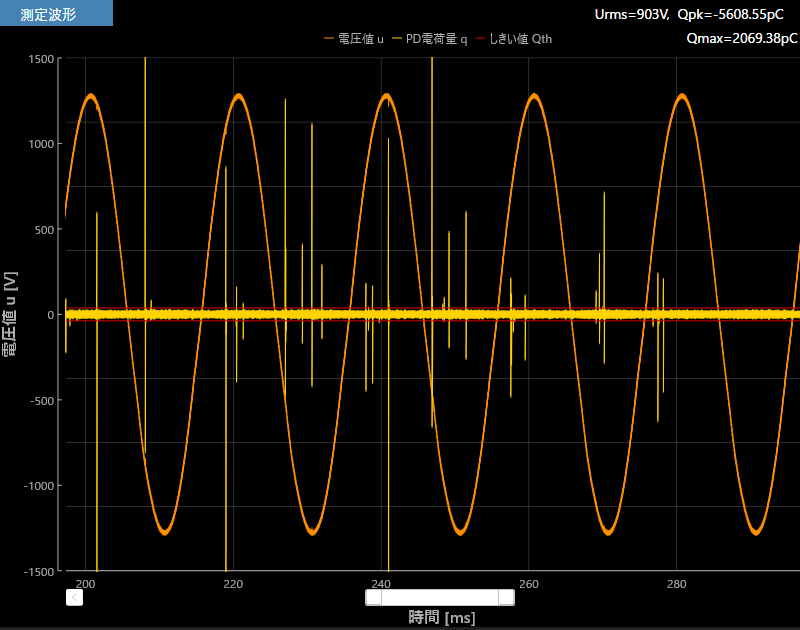 Fig. 8 AC PD test
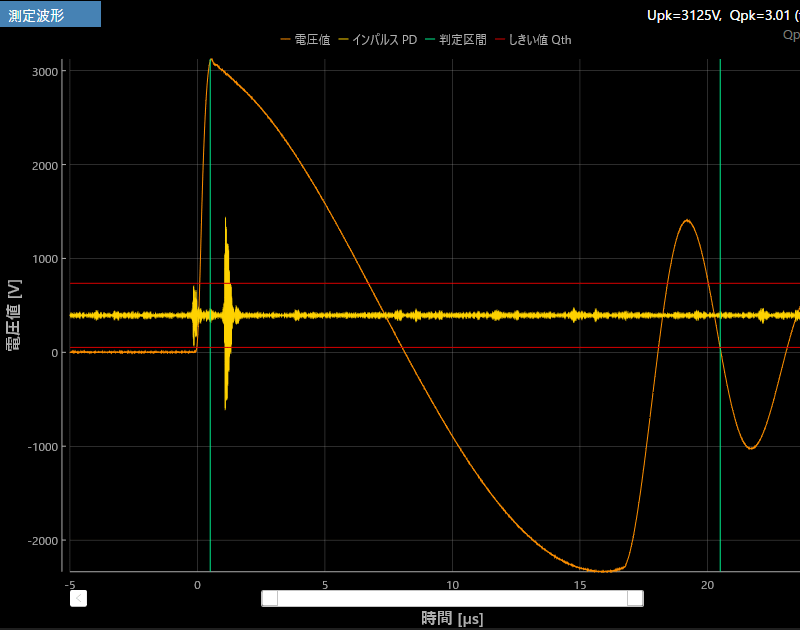 Fig. 9 Surge PD test
For detailed information about partial discharge testing please refer to the links below.
Learn More
 What is Partial Discharge in an Inverter-Driven Motor?
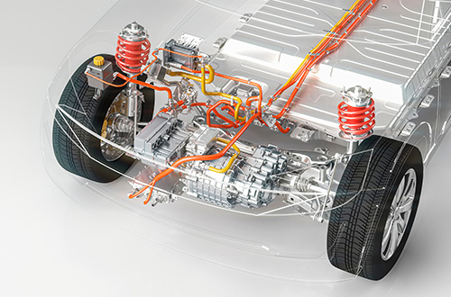 Why is Partial Discharge (PD) Testing Necessary for Inverter-Driven Motors?