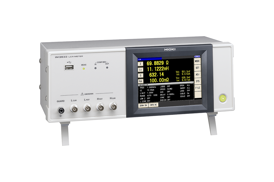
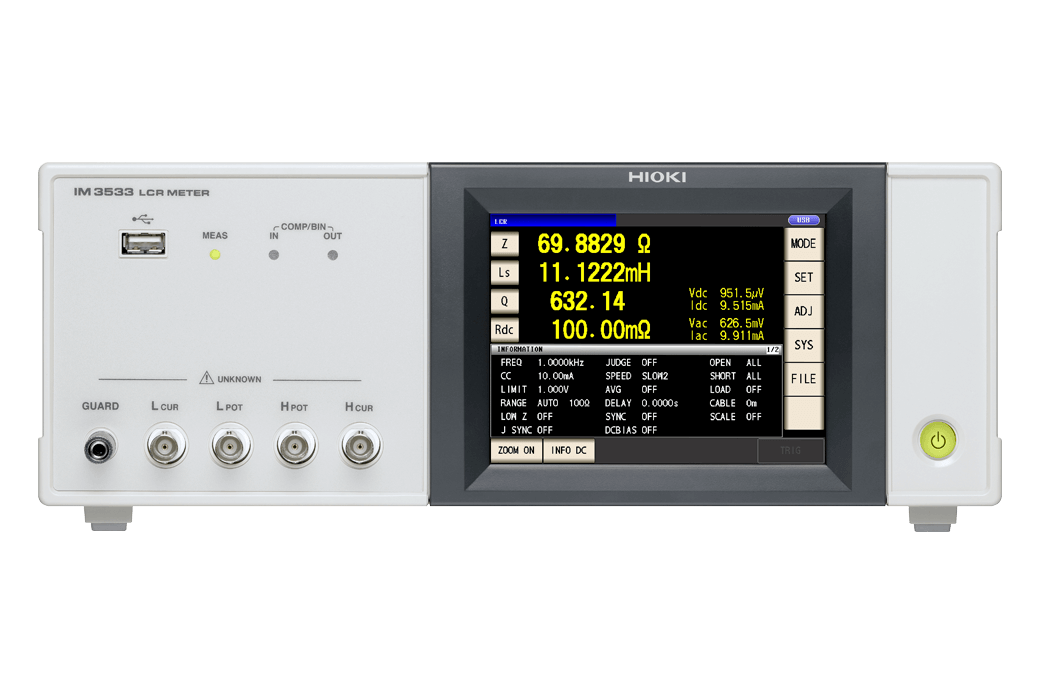
LCR METER IM3533
From R&D Applications to Windings, Coil and Transformer Manufacturing
-

-
 option
 -
 option
 -
 option
 -

-
-

Hioki LCR Meters and Impedance Analyzers range from 1 mHz to 3 GHz devices to suit a wide range of applications in the testing of electronic components. The IM3533 series are Hioki’s first LCR meters to offer turn ratio, mutual inductance and inductance difference measurements of transformers and coils, and are integrated with an internal DC bias to facilitate HDMI compliance testing.
Key Features
- ±0.05% accuracy with wide measurement range
(DC, 1mHz to 200kHz, 5mV to 5V, 10uA to 50mA)
- Non-stop testing over mixed measurement conditions such as C-D and ESR at 10 times the speed of previous models
- Built-in low impedance high precision mode effective for testing low inductance or the ESR of aluminum electrolysis capacitance
- Dedicated modes for measuring transformer winding ratio, mutual inductance and temperature compensated DCR
- Frequency sweep testing (IM3533-01 only)
- 2m/4m cable setting in addition to the standard 0m/1m
- Touch screen with intuitive operation
Model No. (Order Code)
| IM3533 | |
|---|---|
| IM3533-01 | Advanced function model |
LCR Meter IM3533 measurement methods: Continuous measurement using different sets of conditions
The Hioki IM3533 LCR Meter can perform continuous measurement using different capacitor measurement conditions, for example to perform C-D measurement at 120 Hz and ESR measurement at 100 kHz, without stopping to manually change settings.
LCR Meter IM3533 measurement methods: Turn ratio measurement
In transformer and winding measurement, the Hioki IM3533 LCR meter can measure primary-side and secondary-side L values and then calculate and display the turn ratio. This capability eliminates the need to manually calculate this value, as in the conventional approach.
LCR Meter IM3533 measurement methods: Mutual inductance measurement
In transformer measurement, the Hioki IM3533 LCR Meter can perform L measurement with a same-phase series connection and again with a reverse-phase series connection, and then calculate and display the mutual inductance. This capability eliminates the need to manually calculate this value, making it more convenient and efficient than the conventional approach.
LCR Meter IM3533-01 measurement methods: Frequency sweep measurement
The IM3533-01 can perform automatic measurement while sweeping through up to 801 frequencies from a user-specified frequency range or frequency list. Measurement results can be saved on a USB flash drive or computer via the instrument’s interface in order to create lists and graphs of frequency characteristics using the included LCR application software.
Application information
Download the sample application and view the Communications Command User Manual.

Accuracy calculation information
Calculate accuracy by simply entering a numerical value.

Basic specifications
| IM3533 | IM3533-01 | |||||
| Measurement modes | LCR (Measurement with single condition), Transformer testing (N, M, ΔL), Continuous testing(Continuous measurement under saved conditions) (LCR mode) | LCR (Measurement with single condition), Transformer testing (N, M, ΔL), Analyzer (sweep testing), Continuous Testing (LCR/Analyzer mode) | ||||
| Measurement parameters | Z, Y, θ, X, G, B, Q, Rdc (DC resistance), Rs (ESR), Rp, Ls, Lp, Cs, Cp, D (tanδ), N, M, ΔL, T | |||||
| Measurement range | 100 mΩ to 100 MΩ, 10 ranges (All parameters defined in terms of Z.) | |||||
| Displayable range | Z, Y, Rs, Rp, Rdc, X, G, B, Ls, Lp, Cs, Cp : ± (0.00000 [unit] to 9.99999G [unit]) Real value display for Z and Y only θ: ± (0.000° to 180.000°), D: ± (0.00000 to 9.99999) Q: ± (0.00 to 99999.9), Δ%: ± (0.0000% to 999.999%), T: -10.0°C to 99.9°C |
|||||
| Basic accuracy | Z : ±0.05% rdg. θ: ±0.03° | |||||
| Measurement frequency | 1 mHz to 200 kHz (5 digits setting resolution, minimum resolution 1 mHz) | |||||
| Measurement signal level | [Normal mode] V mode, CV mode: 5 mV to 5 Vrms, 1 mVrms steps CC mode: 10 μA to 50 mArms, 10 μArms steps [Low impedance high repeatability mode] V mode, CV mode: 5 mV to 2.5 Vrms, 1 mVrms steps CC mode: 10 μA to 100 mArms, 10 μArms steps |
|||||
| Output impedance | Normal mode: 100 Ω, Low impedance high repeatability mode: 25 Ω | |||||
| Display | 5.7-inch touch-screen color TFT, display can be set to ON/OFF | |||||
| Measurement time | 2 ms (1 kHz, FAST, display OFF, representative value) | |||||
| Functions | DC bias measurement, DC resistance temperature compensation (converted reference temperature display), Comparator, BIN measurement (classify function), Panel loading/saving, Memory function | |||||
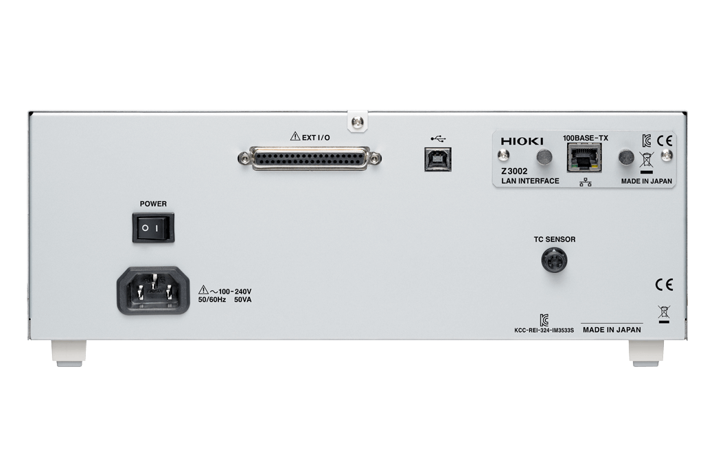
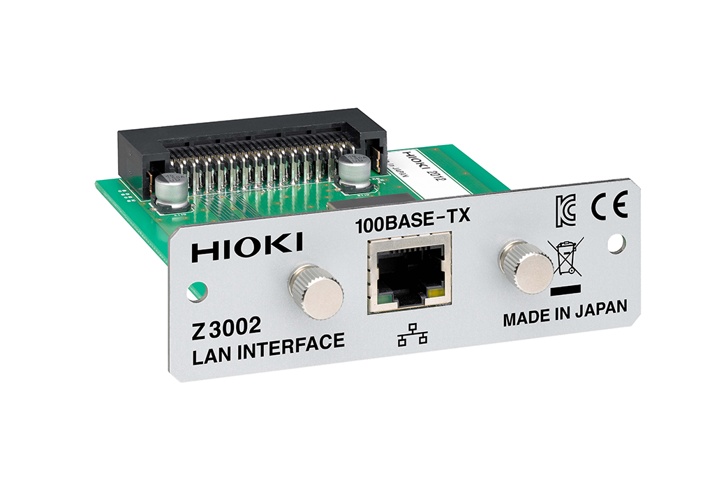
| Interfaces | EXT I/O (Handler), USB communication (high-speed), USB memory Optional: Choose 1 from RS-232C, GP-IB, or LAN |
|||||
| Power supply | 100 to 240 V AC, 50/60 Hz, 50 VA max | |||||
| Dimensions and mass | 330 mm (12.99 in) W × 119 mm (4.69 in) H × 168 mm (6.61 in) D, 3.1 kg (109.3 oz) | |||||
| Included accessories | Power cord × 1, Instruction manual × 1 | |||||
Probe and Test fixtures (15)
When using the 9268-10 or 9269-10, external constant-voltage and constant-current sources are required.
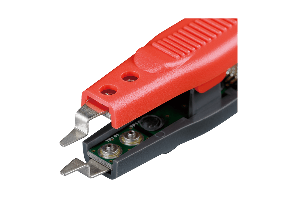
To replace the tip on the L2001, regular size, bundled with the L2001
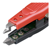
To replace the tip on the L2001, small size
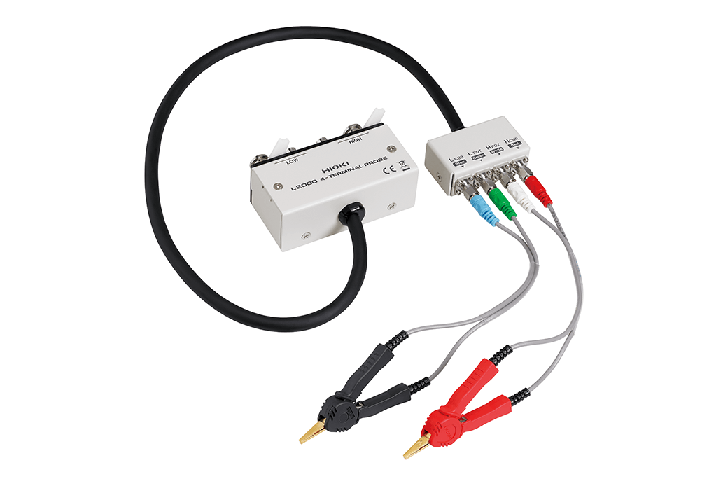
Cable length 1 m (3.28 ft), DC to 8 MHz(Can be measured up to 10 MHz, when combined with the special order model IM3536-01), impedance characteristics of 50 Ω, 4-terminal pair configuration, measurable conductor diameter: ø0.3 (0.01 in) to 5 mm (0.20 in)
Cable length 1 m (3.28 ft), DC to 200 kHz, impedance characteristics of 50 Ω, 4-terminal pair configuration, measurable conductor diameter: ø0.3 (0.01 in) to 5 mm (0.20 in)
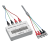
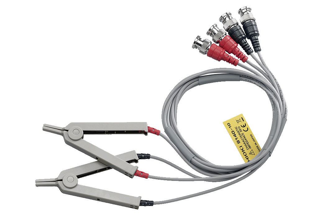
Cable length 1 m (3.28 ft), DC to 8 MHz, impedance characteristics of 50 Ω, 4-terminal pair configuration, measurable conductor diameter: ø0.3 (0.01 in) to 1.5 mm (0.06 in)
Direct connection type, DC to 8 MHz, measurable conductor diameter: ø0.3 (0.01 in) to 2 mm (0.08 in)

Direct connection type, DC to 8 MHz, Test sample dimensions: 1 mm (0.04 in) to 10 mm (0.39 in)
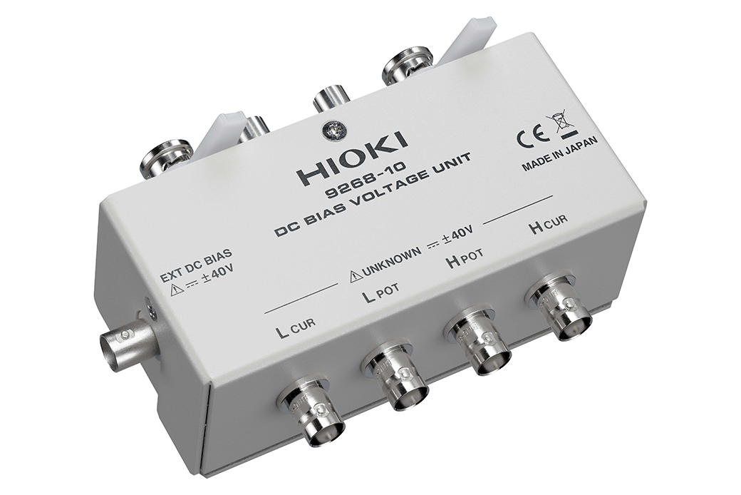
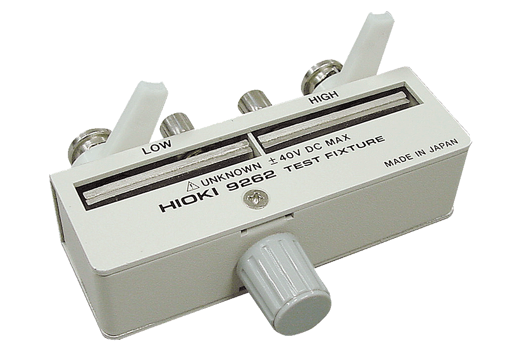
Direct connection type, 40 Hz to 8 MHz, maximum applied voltage of DC ±40 V
Direct connection type, 40 Hz to 2 MHz, maximum applied current of DC 2 A
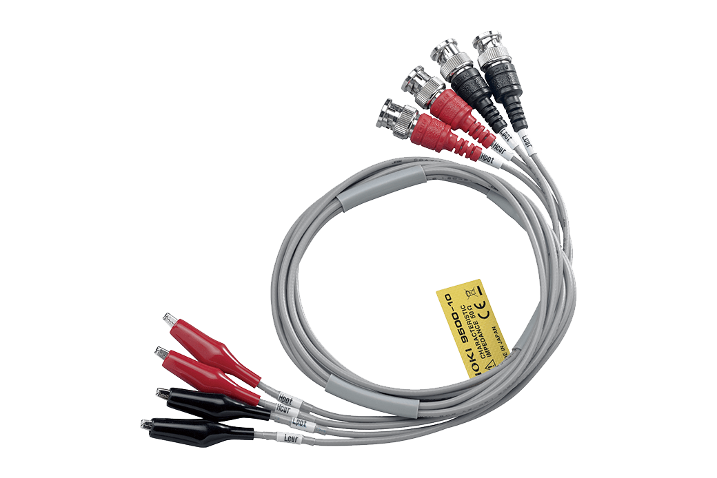
Cable length 1 m (3.28 ft.), DC to 200 kHz, impedance characteristics of 50 Ω, measurable conductor diameter: φ0.3 mm (0.01 in.) to 2 mm (0.08 in.)
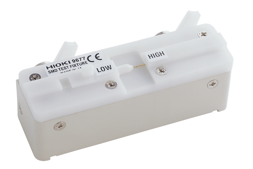
Direct connection type, For measuring SMDs with electrodes on the side; DC to 120 MHz, test sample dimensions: 3.5 mm ±0.5 mm (0.14 in ±0.02 in)
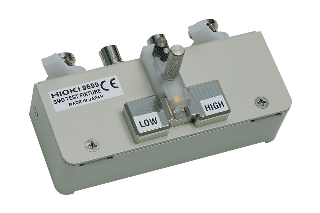
Direct connection type, For measuring SMDs with electrodes on the bottom; DC to 120 MHz, test sample dimensions: 1.0 mm (0.04 in) to 4.0 mm (0.16 in) wide, max. 1.5 mm (0.06 in) high
PC communication (4)
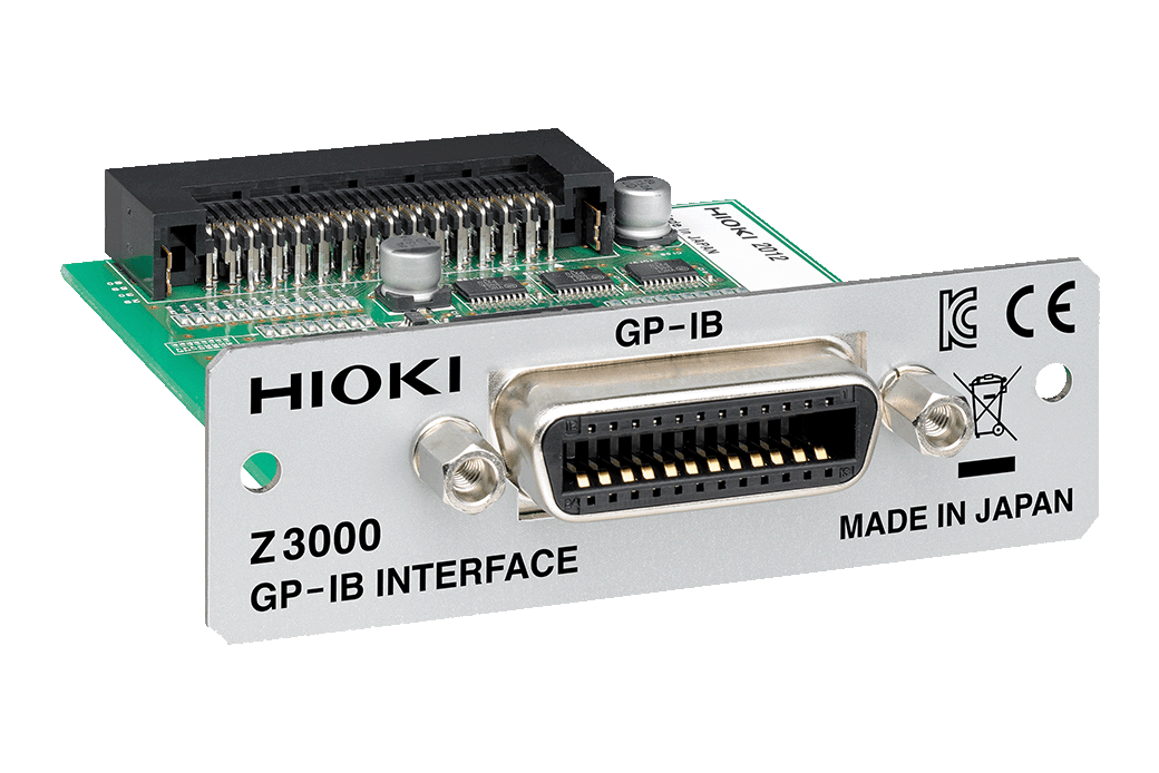
For external control
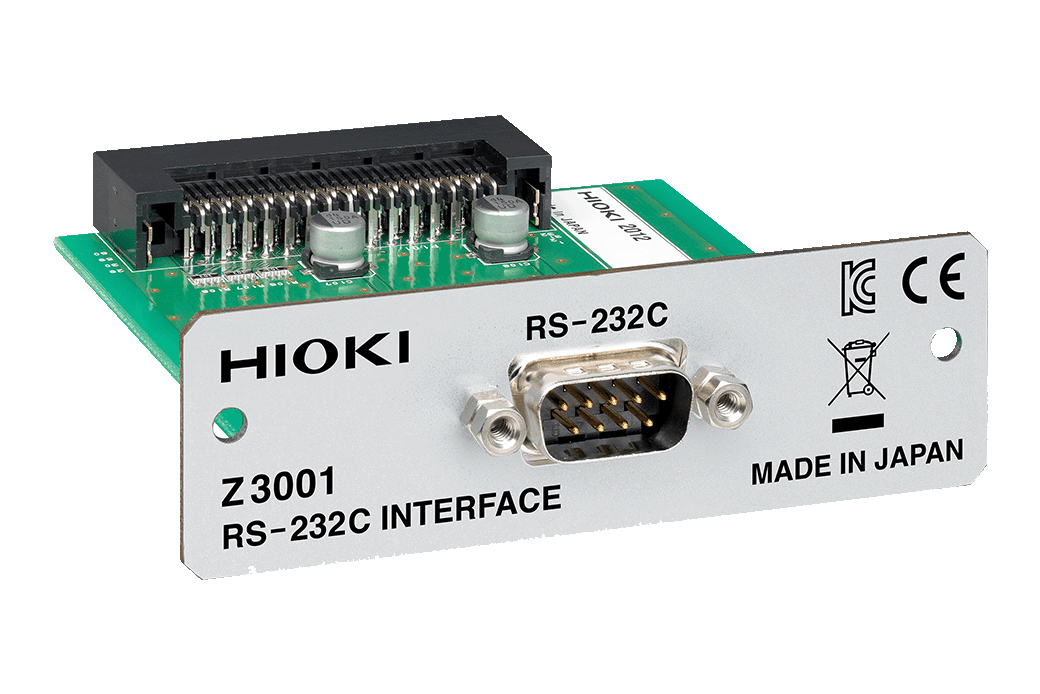
For external control
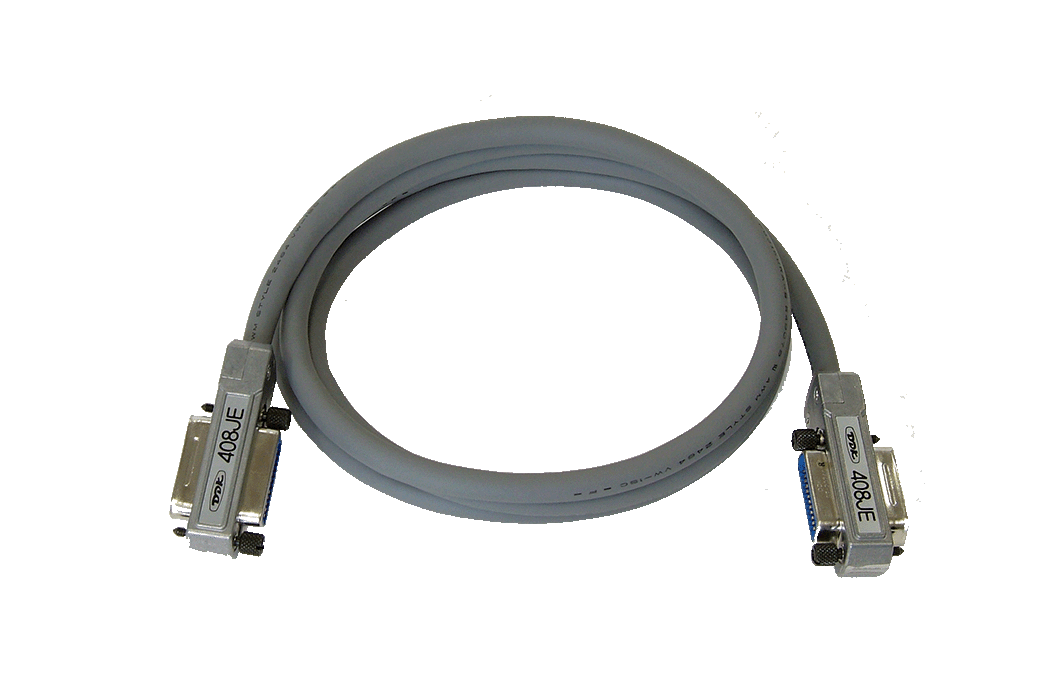
2 m (6.56 ft) length
Temperature probe (1)
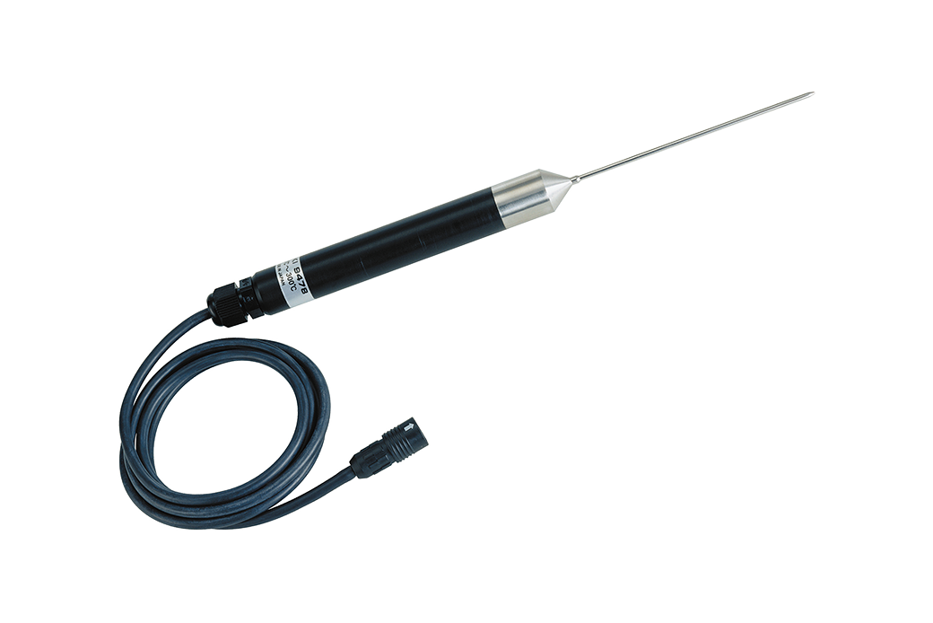
Pt100, Tip dia. φ2.3 mm (0.09 in.), Cord length 1 m (3.28 ft.), Waterproof construction
-
Impedance Measurement Handbook
 English
-
LCR Application Guide
English
-
LCR METER IM3533-01
Test Report
Japanese
English Ver.01 -
LCR METER IM3533
Test Report
Japanese
English Ver.01 -
LCR METER IM3523, IM3523A, IM3533, IM3533-01, IM3536, IMPEDANCE ANALYZER IM3570, IM7580, CHEMICAL IMPEDANCE ANALYZER IM3590
Communication Instruction Manual
English
Ver.09
-
LCR METER IM3533 IM3533-01
Instruction Manual
English
Ver.07
-
LCR METER IM3533,IM3533-01
Instruction Manual
Simplified Chinese
Ver.06
-
LCR METER IM3533,IM3533-01
Instruction Manual
Korean
Ver.03
-
LCR METER IM3533-01
Ver.02
-
LCR METER IM3533
Ver.02