Double Pulse Testing of SiC/GaN device
A Comparison of Coaxial Shunts, Rogowski Coils, and AC/DC Current Probes
Introduction
Accurate current waveform measurement matters in WBG device evaluation
Wide-bandgap semiconductors such as SiC and GaN enable higher efficiency and greater power density in power converters thanks to their fast switching performance. At the same time, their steep current transitions make it more difficult to accurately capture waveform characteristics such as peak current, di/dt, ringing, and reverse-recovery current.
In double pulse testing, voltage and current waveforms are measured simultaneously to evaluate turn-on and turn-off behavior, as well as switching losses. As a result, limited current-measurement bandwidth, propagation delay, noise, and offset drift can directly affect the measurement results.
This article compares AC/DC current probes, coaxial shunts, and Rogowski coils, and highlights the key points to consider when selecting a current measurement method for double pulse testing of WBG devices.
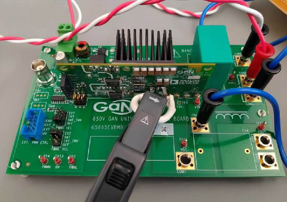 GaN Switching Characteristic Evaluation Board
Current waveforms measured in double pulse testing
What to observe during turn-on, turn-off, and reverse recovery
In double pulse testing (DPT), a power device is driven with short pulses to capture transient switching waveforms. The first pulse builds current in the load inductor. The turn-off behavior is then evaluated at the end of the first pulse, while the turn-on behavior is evaluated at the beginning of the second pulse.
The main current waveforms to observe include inductor current, current transitions during turn-on and turn-off, peak current, di/dt, ringing, and reverse-recovery current. These current waveforms are also used, together with voltage waveforms such as Vds or Vce, to calculate instantaneous power and switching-loss parameters, such as Eon and Eoff.
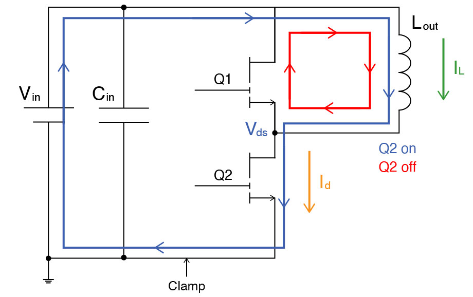 Double Pulse Test Circuit Diagram
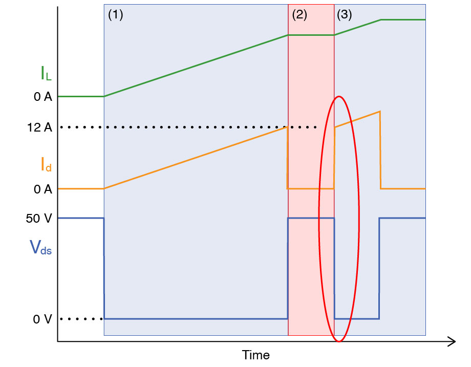 Waveform Characteristics of Double Pulse Test
As a result, measurement errors such as reduced apparent slew rate, inaccurate peak-current capture, damped ringing, or timing skew relative to the voltage waveform can directly distort the evaluation of switching behavior.
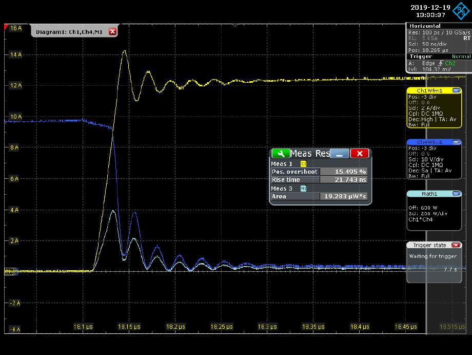 Measurement results of switching characteristics
Yellow: Current waveform Id, Blue: Voltage waveform Vds, Light blue: Power calculation waveform (current waveform × voltage waveform)
Comparison of current measurement methods
The most common current measurement methods used in double pulse testing are AC/DC current probes, coaxial shunts, and Rogowski coils. Each can be an effective solution, but because their operating principles and connection methods differ, their strengths, limitations, and practical considerations also differ.
AC/DC current probe
- Advantages
Clamp-on AC/DC current probes are easy to connect and help minimize circuit modification. They can also measure current waveforms that include a DC component. - Key considerations
Important parameters to check include bandwidth, maximum current, frequency derating, and probe delay. - Typical applications
Typical uses include DPT condition setup, waveform observation, design evaluation, debugging, and comparative measurements.
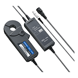
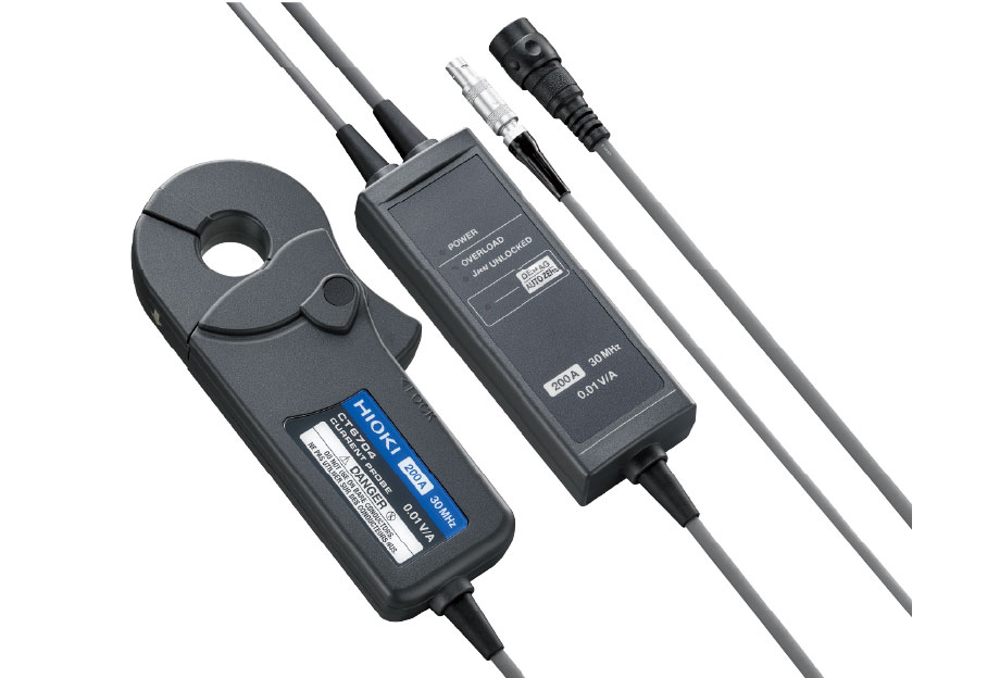
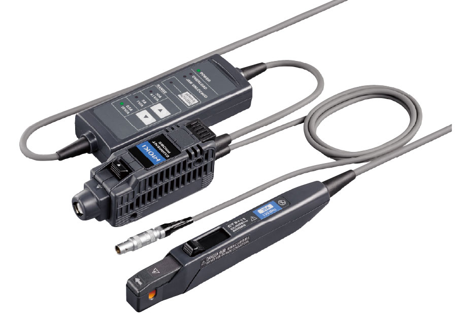 Current probe CT6711
Coaxial shunts / CVRs
- Advantages
They offer high bandwidth and low delay, making them well suited for detailed observation of fast transient currents. - Key considerations
They must be inserted into the circuit. Their performance can be affected by parasitic inductance, self-heating, insulation requirements, grounding conditions, and fixture design. - Typical applications
Typical uses include precise switching-loss evaluation and high-bandwidth reference measurements.
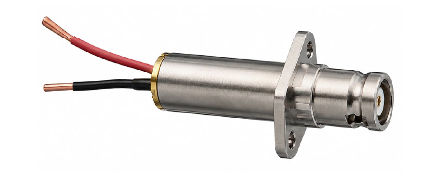 Coaxial shunt
Rogowski coils
- Advantages
They are well-suited for measuring large pulsed currents. Their flexible form factor makes them easy to install, and they have minimal insertion loss in the circuit. - Key considerations
They cannot measure DC current components and require an integrator circuit. Their results are also more susceptible to low-frequency limitations, noise, and sensor position effects. - Typical applications
Typical uses include checking overall trends in large pulsed currents and making approximate current measurements in wiring or busbars.
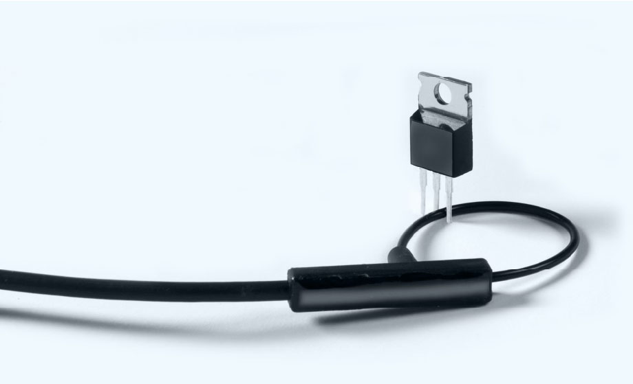 Rogowski coil*1
Measured waveform comparison
Differences in current rise waveforms across measurement methods
In this evaluation, current rise waveforms measured under identical conditions were compared using the pulse generator output signal as a reference. The three methods compared were a coaxial shunt, an AC/DC current probe, and a Rogowski coil.
| Measurement Method | Bandwidth Specification |
|---|---|
| Coaxial Shunt | 2 GHz |
| AC/DC Current Probe | 120 MHz |
| Rogowski Coil | 30 MHz |
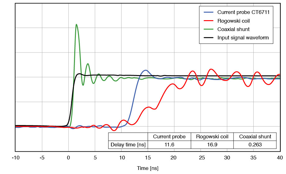 Reference signal: 1 ns rise-time pulse
The waveform measured with the coaxial shunt showed the smallest delay relative to the reference signal, capturing the current rise with the fastest response. At the same time, it exhibited a large overshoot. This suggests that insertion effects, connection conditions, and parasitic elements must be considered when using this method.
The AC/DC current probe waveform lagged the reference signal. Its rising edge was also slightly more gradual than that of the coaxial shunt, likely due to the probe’s bandwidth limit. Even so, overshoot was small, and the overall waveform remained stable, providing a practical and easy-to-interpret view of the current rise behavior.
With the Rogowski coil, ringing appeared even before the current signal began to rise. Oscillatory components were also observed during and after the rising edge, and the rise itself was more gradual. These characteristics may be influenced by the coil’s bandwidth limit, the integrator circuit, and installation conditions.
In short, each method has clear trade-offs. The coaxial shunt provides the fastest response, the Rogowski coil offers flexibility for large-current measurements, and the AC/DC current probe delivers the best balance of practicality and waveform stability for many DPT tasks.
Key points when selecting a current measurement method
Look beyond bandwidth and evaluate the entire measurement setup
In double-pulse testing, a current-measurement method should not be selected solely on the basis of bandwidth. The choice should be made based on the full measurement requirement, including the evaluation objective, current level, whether DC components must be measured, the impact on the circuit, ease of connection, and safety.
| Items | What to check |
|---|---|
| Objective | Eon/Eoff analysis, or simple waveform observation, condition setup, and debugging. |
| Bandwidth | Current rise time, peak current, and ringing frequency |
| Maximum current | Allowable measurement range of the pulse and peak currents |
| DC measurement | DC measurement is required for ripple rate measurement |
| Insertion loss | Connection of the measuring instrument causes parasitic inductance, resulting in waveform changes |
| Delay / deskew | The current waveform response has sensor-specific delay |
| Connectivity / repeatability | SeSet upor repeated measurements at the same position and conditions |
| Safety | Ratings, insulation, and handling under high voltage and high current conditions |
In particular, when calculating switching losses such as Eon and Eoff, time alignment between the voltage and current waveforms is critical. Even a small delay in the current waveform can affect the instantaneous power calculation. Before measurement, the delay difference between the voltage probe and the current measurement path should be checked, and deskew should be applied if necessary.
When using an AC/DC current probe, basic preparation includes zero adjustment, confirming current direction, and setting the appropriate range. For waveforms containing high-frequency, high-current components, frequency derating must also be checked carefully. It is important to evaluate not only the maximum current stated in the catalog, but also whether the probe can operate within its allowable range at the relevant frequency content.
DPT involves high voltages and large currents, and hazardous energy can remain stored in the test circuit during and after operation. Any change to the measurement setup should be made only after power has been turned off and residual charge in capacitors has been verified. Safety covers, interlocks, insulated fixtures, and appropriate personal protective equipment should be used so that the operator cannot come into contact with energized parts during the test.
Conclusion
Choose the current measurement method based on your test objective
- Current probe CT6711: 120 MHz bandwidth
 Current Probe CT6704: 30 MHz badwidth
In double pulse testing, the quality of the observed current waveform has a major impact on the evaluation of switching behavior. To accurately assess parameters such as peak current, di/dt, ringing, reverse-recovery current, and switching losses including Eon and Eoff, it is important to understand not only the device under test, but also the characteristics of the current measurement method itself.
Coaxial shunts are effective for high-bandwidth measurements with minimal delay. However, they also require careful consideration of circuit insertion, parasitic elements at connection points, self-heating, insulation, and safety. Rogowski coils can be useful for observing large pulsed currents, but they cannot measure DC components, and in fast rising waveforms, attention must be paid to ringing and reduced waveform sharpness.
AC/DC current probes do not offer the same bandwidth as coaxial shunts, but they can be connected with a clamp-on structure and can measure current waveforms that include DC components. In the comparison presented here, they were also shown to capture the current rise waveform required for double pulse testing in a stable manner while minimizing circuit modification.
The key is to choose the measurement method according to the test objective. Detailed loss analysis, waveform verification, condition setup, and design debugging each place different demands on the measurement system. It is therefore important to evaluate the entire setup, including bandwidth, current rating, DC measurement capability, circuit impact, deskew, and safety.
Hioki offers a lineup of AC/DC current probes for oscilloscope use. For applications such as double-pulse testing of WBG devices, inverter evaluation, and DC/DC converter evaluation, Hioki provides current probes tailored to the required measurement conditions for observing fast current waveforms.
If you need assistance selecting a current probe suitable for double pulse testing of WBG semiconductors or for observing high-speed current waveforms, please feel free to contact us. We will propose the optimal measurement configuration according to your measurement conditions, please contact us.