Ensuring Safe Load Rejection Testing in Hydroelectric Power Plants
Risk of Load Rejection
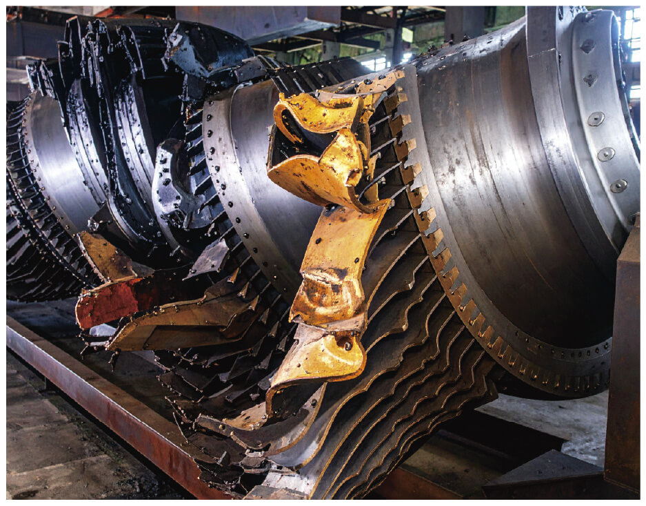
Imagine a hydroelectric power plant humming with energy, its turbines spinning steadily under the force of cascading water—until suddenly, a fault in the transmission line or control system causes an abrupt load rejection. The generator's demand plummets, sending turbine speeds skyrocketing and risking catastrophic damage from vibrations, blade failures, or surging water pressure that could rupture massive pipelines. These aren't just theoretical threats; they're real hazards in systems where even minor failures can escalate into life-threatening accidents.
Potential of Hydroelectric Power
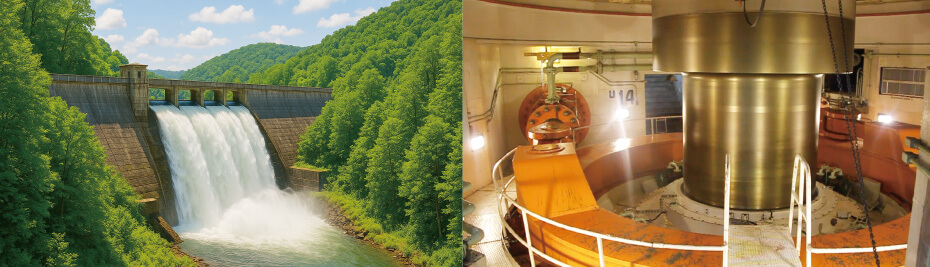
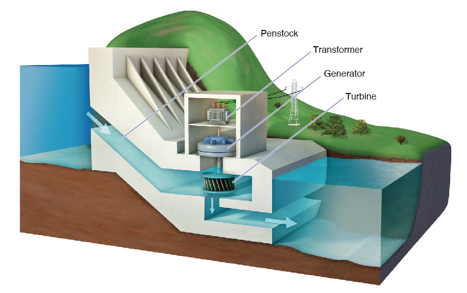
Hydroelectric power remains a cornerstone of renewable energy, with over 36,000 dams worldwide providing stable, carbon-free electricity that's immune to weather fluctuations and adaptable to demand shifts. These plants harness water’s potential energy, channeling it through turbines to generate electricity. However, maintaining safe and reliable operation requires regular testing, such as load rejection tests, to verify safe shutdown under sudden load loss.
Mechanism of Load Rejection Testing
Hydroelectric power plants are critical infrastructure, delivering reliable electricity to grids worldwide. To maintain this reliability, regular maintenance and testing are essential. One key procedure is the load rejection test, which verifies that a generator can safely stop when the load is suddenly disconnected. This test is essential after turbine repairs, governor maintenance, or generator overhauls. When a load is removed, the turbine’s rotational speed increases, posing risks such as damage if not controlled. The governor adjusts the guide vanes to reduce water flow, slowing the turbine to a safe stop. However, closing the guide vanes too quickly can spike water pressure, potentially damaging the penstock. Engineers must monitor parameters like turbine speed, water pressure, guide vane position, generator voltage, and current to ensure safe operation and document results for compliance.
Testing Method
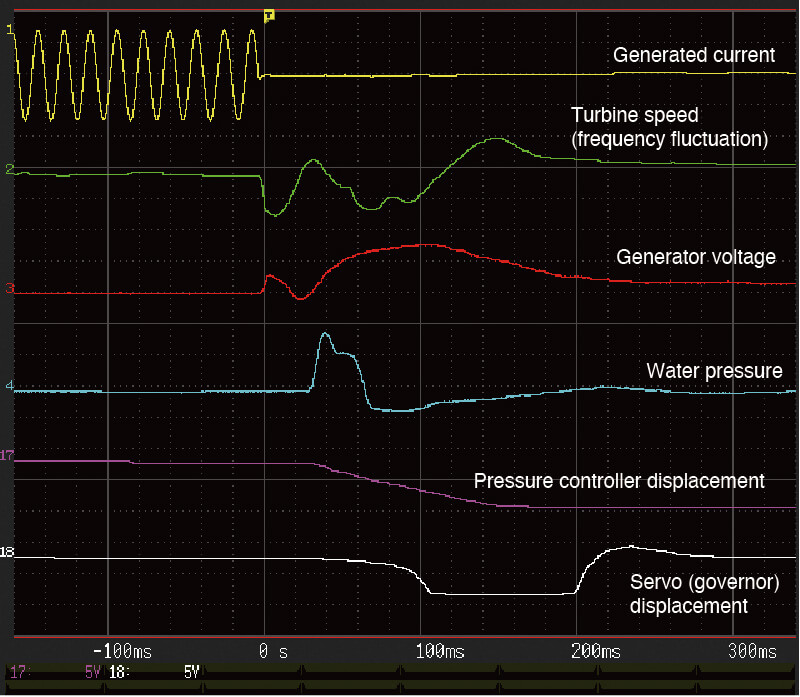
To conduct a load rejection test, engineers connect sensors measuring turbine speed, water pressure, guide vane position, and other parameters to a data recording device. When the load is disconnected, the device captures signals like generator voltage, current, and governor servo outputs. Advanced recorders like the Memory HiCorder with versatile trigger functions can start measurements at precise moments, such as when the control signal changes or voltage drops, ensuring accurate data capture. As the load is removed, turbine speed rises, prompting the governor to gradually close the guide vanes, reducing speed until the turbine stops. If the device records these dynamics as waveforms, engineers can analyze peak turbine speed, maximum water pressure, and valve behavior. Tools like multiple cursors and numerical calculations found in the HiCorder simplify extracting critical values, such as maximum values or time differences, ensuring the system operates within safe limits.
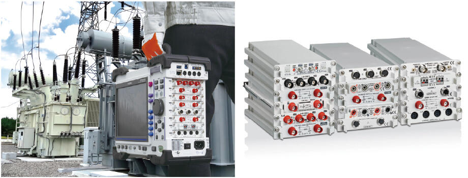
Measurement Configuration Example
A typical setup includes:
- Memory HiCorder MR8848: simultaneously records and displays multiple signals
- Analog Unit 8966: measures generator voltage
- 3CH Current Unit U8977: measures generator current
- Frequency Unit 8970: measures turbine rotational speed
- Strain Unit U8969: measures water pressure or valve stroke
This modular approach allows customization to specific test needs, ensuring flexibility across different hydroelectric plants
Download of software
The free software “MR6000 Viewer” can be downloaded here.
For detailed product information, please visit our website.
For a demonstration or consultation on a specific application, please contact us using our contact form.