Camera Module Testing System
This paper introduces a system that enables high-speed testing of camera modules, for which demand is growing in in-vehicle devices and smartphones, while accommodating fast setup changes on the production line and software creation.
Growing Demand in Smartphones and Vehicle Applications
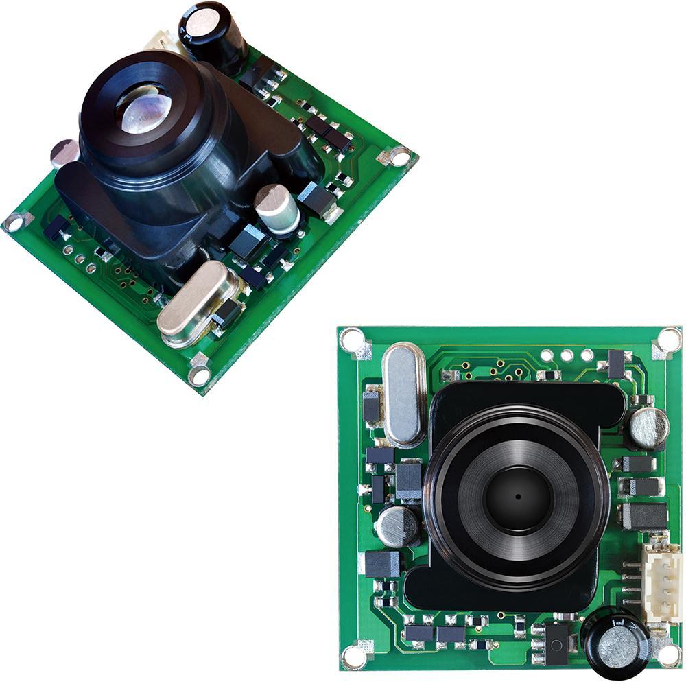
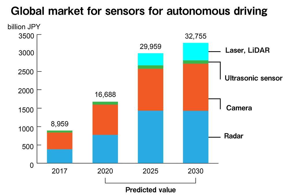
As adoption of smartphones fuels demand for image sensors, automotive applications such as self-driving vehicles will also push up production volume of the sensors. Production of camera modules, which incorporate an image sensor on an electronic circuit board, is growing due to their small size and the ease of embedding.
Camera modules are often used in important devices where malfunctions are unacceptable, and where high quality and high reliability are a must. Consequently, it will be key to deliver quality improvements at manufacturing facilities as well as reduced testing takt times as production volumes grow.
This paper introduces a system that can accelerate testing between production processes of camera modules while facilitating fast setup changes on the production line and test software creation to accommodate changes in the models being produced.
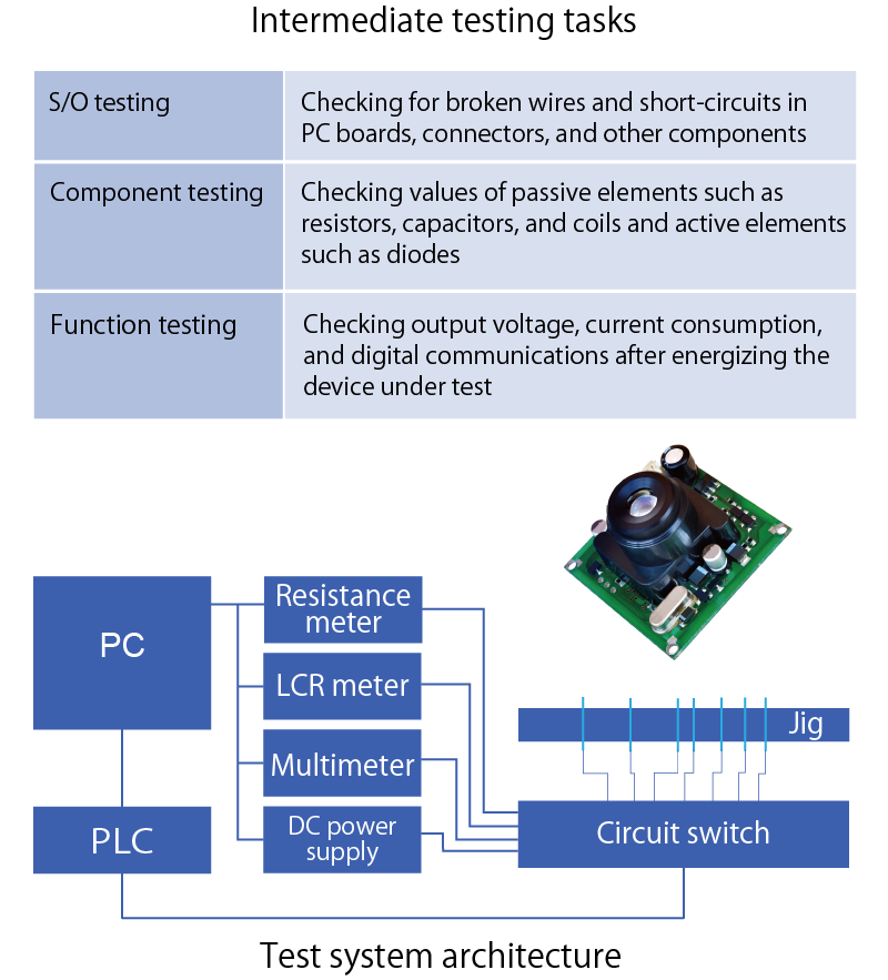
Issues in Camera Module Intermediate Testing
Tests between production processes are also known as intermediate tests. The intermediate tests of camera modules consists of the tests described in the table to the right.
In the past, testing systems consisted of a “bed-of-nails” fixture with a probe for each test point, a relay circuit for switching circuits, measurement instruments (such as a resistance meter, multimeter, and LCR meter), a DC power supply, a computer or PLC to control these components, and a program to execute test sequences. This approach suffers from the following issues:
- Inability to shorten test cycle time due to the difficulty of switching circuits and synchronizing measurement instrument control
- Significant amount of time required to create test sequences for different models DUTs because programs lack versatility
- Significant amount of time required to identify issues underlying equipment failures (poor maintainability)
Realizing High-speed Testing and High Maintainability
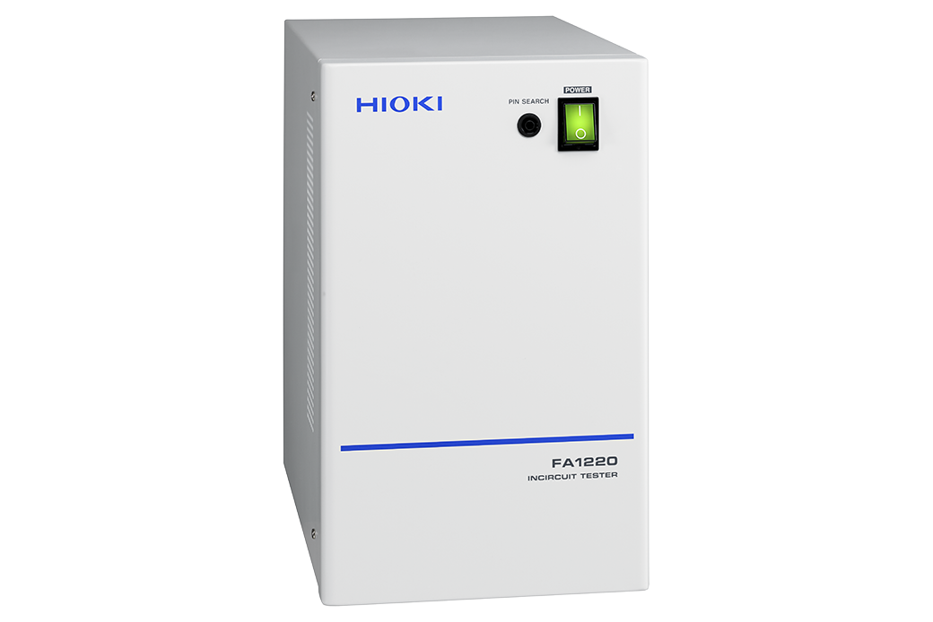
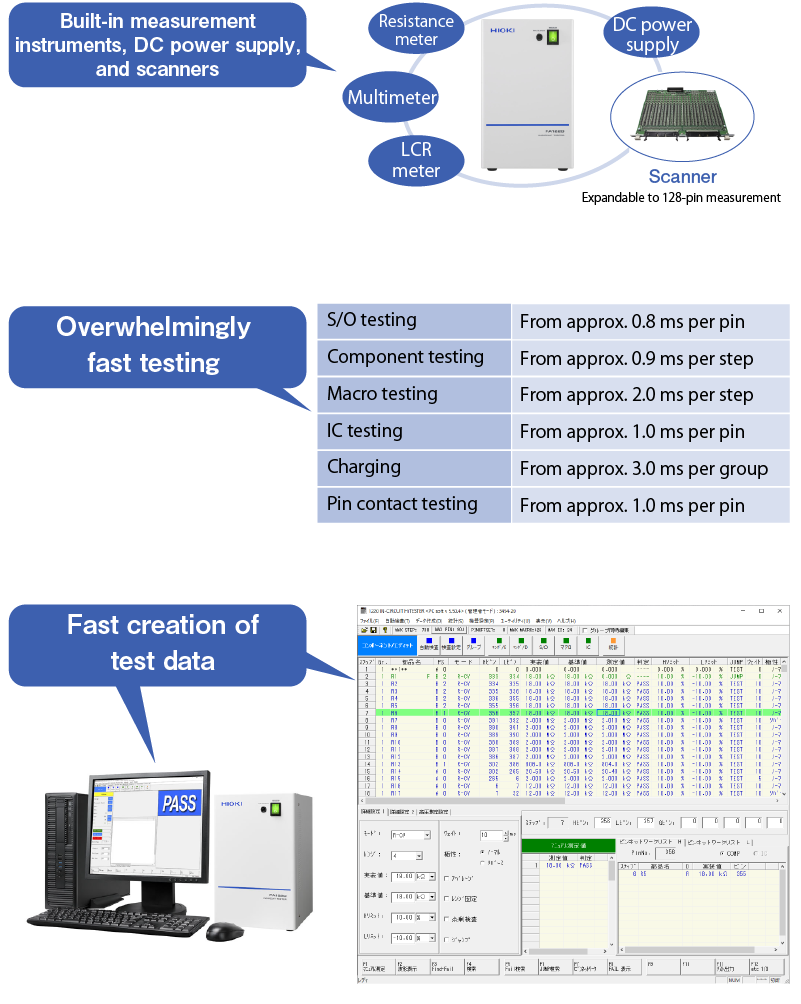
The In-Circuit Tester FA1220 is a combination of a circuit-switching device (scanner), electric measurement instruments, and a DC power supply inside a compact enclosure. It operates according to test sequences created using a desktop software in order to successfully address challenges posed by intermediate testing of camera modules.
- High-speed testing is made possible by the optimized synchronization of the system’s built-in scanner, measurement circuit boards, and power supply.
- Create test data in a short period of time using the system’s software.
- Self-test functionality can automatically identify issues in the event of equipment failure.
- Self-test functionality can prevent erroneous judgments and shipment of defective products.
- Create test data in a short period of time using the system’s software.
- Self-test functionality can automatically identify issues in the event of equipment failure.
- Self-test functionality can prevent erroneous judgments and shipment of defective products.
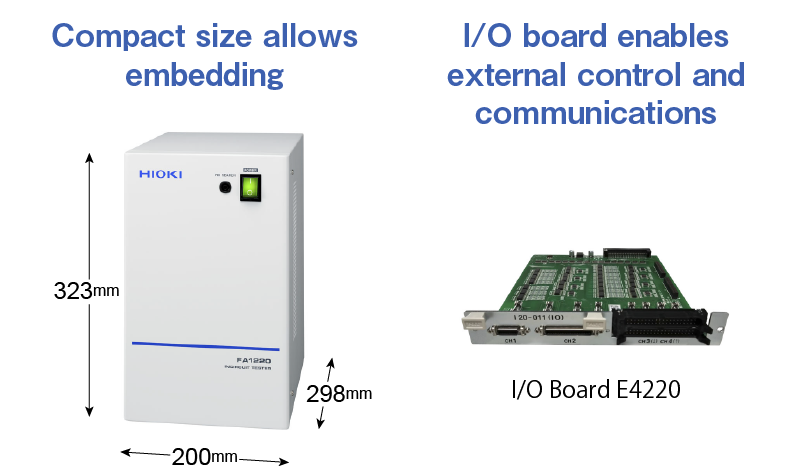
Functionality and Concept that Make it Possible to Embed the FA1220 into Other Equipment
Despite its compact size, the In-Circuit Tester FA1220 has the ability to be customized with additional scanners for measurement of up to 1,024 pins.
An I/O board allows the system to be controlled from an external source. For example, an external device can start the testing or receive the judgment results.
In this way, the FA1220’s functionality and specifications well-suited to integration into the user’s own systems.
An I/O board allows the system to be controlled from an external source. For example, an external device can start the testing or receive the judgment results.
In this way, the FA1220’s functionality and specifications well-suited to integration into the user’s own systems.