Multi-layer Ceramic Capacitors (MLCC)
What are Multi-Layer Ceramic Capacitors (MLCC)?
There are two types of MLCC: a high-dielectric-constant type whose capacitance varies with the measurement voltage and a temperature-compensated type whose capacitance does not vary. The measurement conditions used when defining capacitance are set forth by separate JIS standards for temperature-compensated and high-dielectric-constant MLCCs.
Setting example of measurement conditions
*Otherwise, default settings are used.
*The above settings apply to an example measurement. Since optimal conditions vary with the measurement target, specific settings should be determined by the instrument operator.
IEC 60384-21 Fixed surface mount multilayer capacitors of ceramic dielectric(JIS C5101-21)
Class 1: Temperature compensating type (EIA type C0G, JIS type CH etc.)(IEC30384-21)
IEC 60384-22 Fixed surface mount multilayer capacitors of ceramic dielectric(JIS C5101-22)
Class 2: High dielectric constant type (EIA type X5R, X7R, JIS type B, F etc.)(IEC30384-22)
*1 The measurement voltage (i.e., the voltage applied to the sample) is the voltage obtained by dividing the open-terminal voltage by the output resistance and the sample.
*1 The measurement voltage (i.e., the voltage applied to the sample) can be calculated based on the open-terminal voltage, the output resistance, and the sample’s impedance.
*2 CV mode is convenient when measuring a sample whose impedance is unknown and when measuring multiple samples that exhibit a large degree of variability.
High-dielectric-constant capacitors
Capacitors bearing temperature characteristics such as B, X5R, and X7R use high-dielectric-constant materials.
While high-dielectric-constant capacitors can deliver high capacitance in a small package, their capacitance tends to vary greatly with the measurement voltage and temperature.
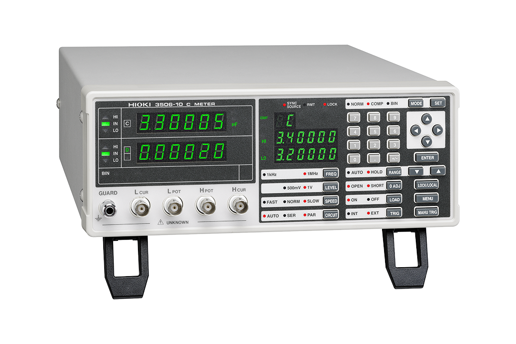
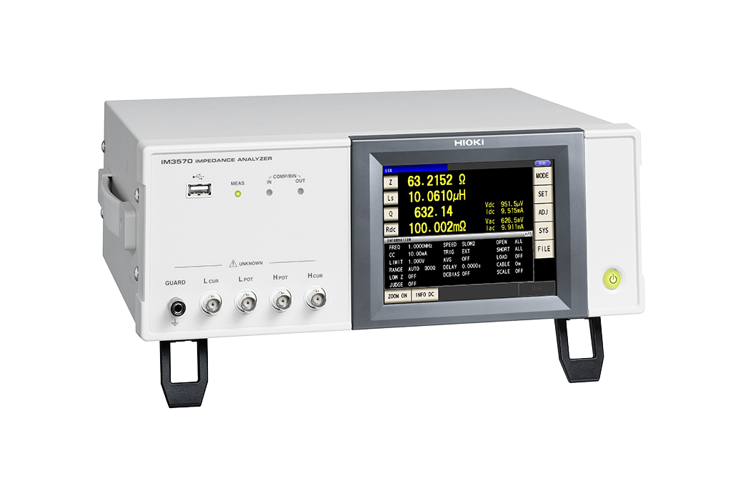
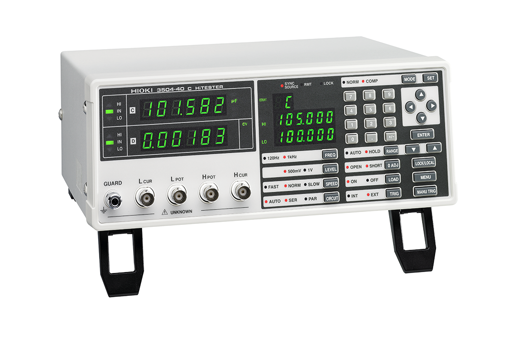
Products used
Mass Production Applications
Research and Development Applications
*For more information, plese see the product catalog.
Selecting Parameter, Cs or Cp
Impedance according to frequency (when D is sufficiently small)
Generally speaking, series equivalent circuit mode is used when measuring low-impedance elements (approximately 100Ω or less) such as high-capacity capacitors, and parallel equivalent circuit mode is used when measuring high-impedance elements (approximately 10 kΩ or greater) such as low-capacity capacitors.
An actual capacitor will behave as though Rs and Rp have been connected in series and in parallel, respectively, with the ideal capacitor C, as in the figure. Rp is usually extremely large (megaohm-order or greater), and Rs is extremely small (several ohms or less). An ideal capacitor’s reactance can be calculated using the following equation based on its capacitance and frequency: Xc=1/j 2πf C[Ω]. When Xc is small, the impedance when Rp is placed in parallel can be considered to be approximately equal to Xc. On the other hand, because Rs cannot be ignored when Xc is small, the overall setup can be treated as a series equivalent circuit with Xc and Rs. By contrast, when Xc is large, Rp cannot be ignored but Rs can, so the setup can be treated as a parallel equivalent circuit.