How to Measure Resistance
Learn about resistance measurement
Electrical resistance plays an extremely important role in the circuitry of electronic devices. Such devices may malfunction if the resistance in their circuitry diverges from the proper level. However, electricity is not visible. A specialized measuring instrument is necessary in order to investigate whether a circuit has the proper resistance.
An instrument such as a tester is necessary in order to measure resistance, but how is such measurement carried out? This page provides a detailed introduction to how a tester or multimeter can be used to measure resistance.
How is resistance measured?
Resistance is measured using an instrument such as an analog multimeter or digital multimeter. Both types of instrument can measure not only resistance, but also current, voltage, and other parameters, so they can be used in a variety of situations.
However, resistance measurement does not involve measuring the circuit’s resistance value itself. Instead, resistance is calculated by measuring the current and voltage applied to the circuit. When a current is applied to the circuit under measurement, the circuit (resistance) exhibits a voltage (or more precisely, a voltage drop). Resistance can be calculated by measuring the current and voltage using Ohm’s Law.
As a result, a circuit’s resistance value can be determined if the current and voltage measured values are known. Analog multimeters and digital multimeters employ the measurement principle of Ohm’s Law to measure resistance.
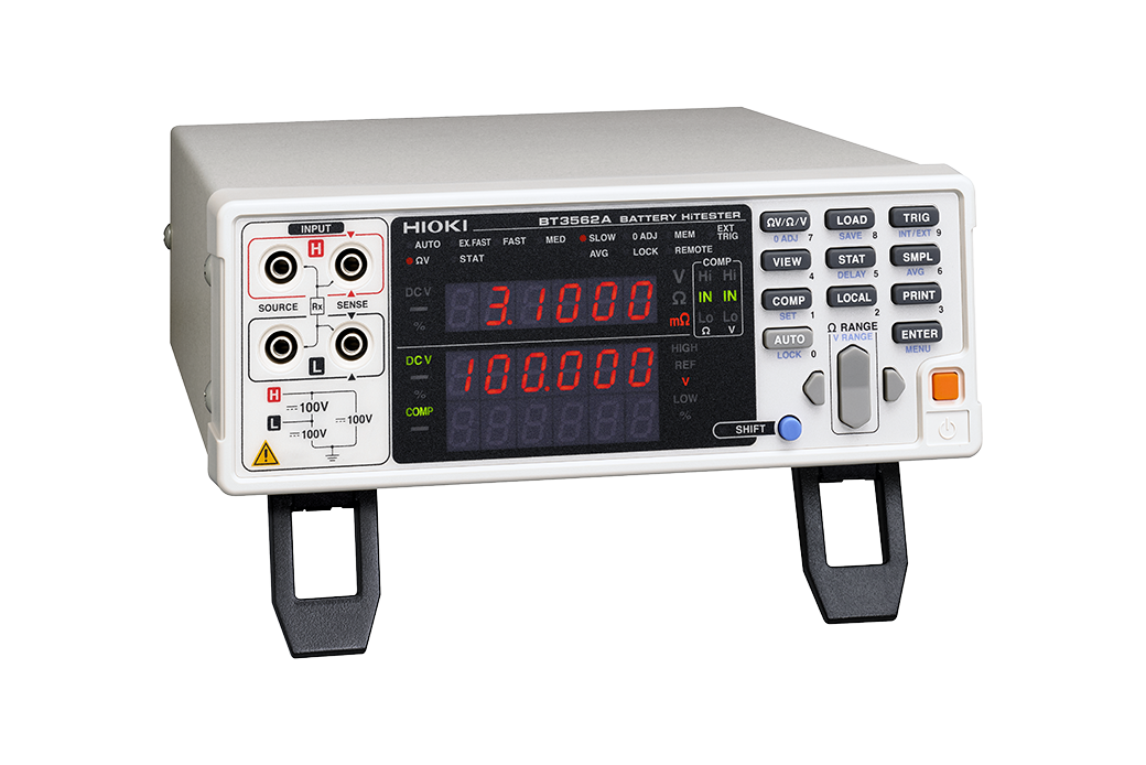
Instruments for measuring electrical resistance
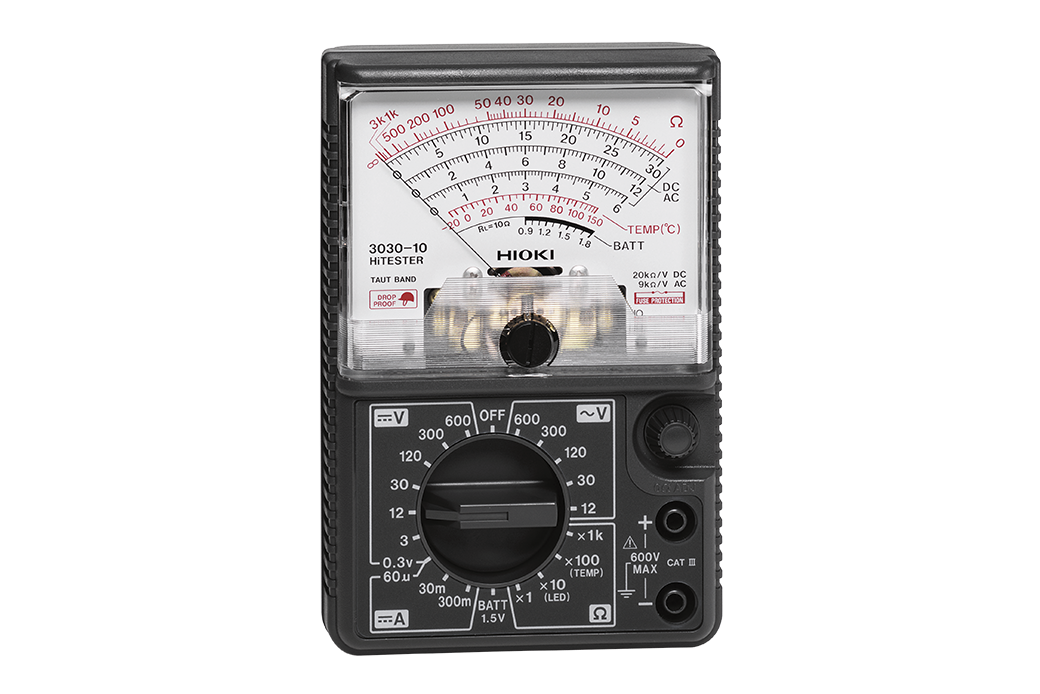
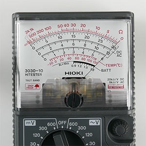
How to find resistance with an analog tester
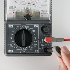
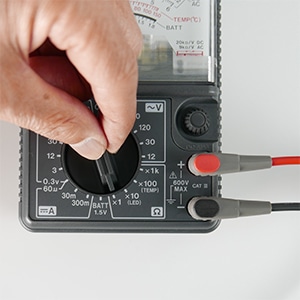
When measuring resistance with an analog multimeter, switch off power to the circuit under measurement. Plug the red test lead into the positive input terminal with the “+” mark and the black test lead into the COM input terminal. Switch the instrument to Ω mode and set the range button as appropriate based on the circuit’s anticipated resistance.
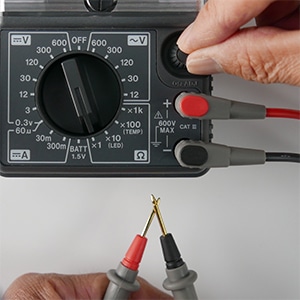
Short the black and red test pins and set the needle to 0 Ω using the 0 Ω adjustment knob. Then place the red and black test pins in contact with both ends of the circuit under measurement and read the value indicated by the meter.
Keep in mind that applying a voltage to the test leads while the instrument is set to resistance mode could damage the tester. Additionally, if you are unable to perform 0 Ω correction, the analog multimeter’s battery may be low. If you encounter this issue, check the battery's voltage.
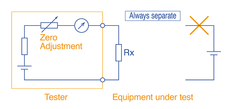 Resistance measurement circuit of an analog meter
Always conduct zero adjustment when measuring resistance. (Mechanical and electrical zero adjustment)
Situations where voltage is being applied is hazardous, therefore separation is critical.
How to measure resistance with multimeter
In general, resistance is measured with a digital multimeter in the same manner as with an analog multimeter, and it’s a very simple process. The only difference is that the value is indicated digitally instead of by an analog needle; otherwise, the basic method is mostly the same. However, digital multimeters support two measurement methods:
In most cases, when measuring resistance with a digital multimeter, you’ll use the two-terminal measurement method. This method applies a constant current and measures the resistance value using the instrument’s voltmeter. This method is the same as that used by analog multimeters. However, two-terminal measurement has the disadvantage of yielding resistance values that include the wiring between the instrument and the circuit under measurement.
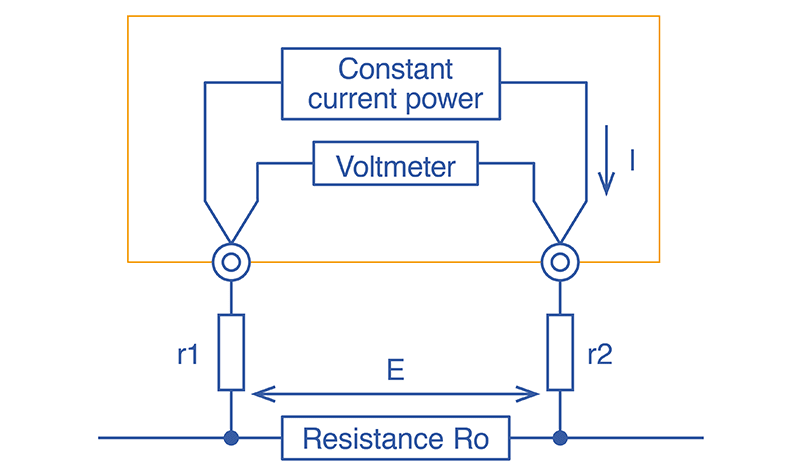 Two-terminal measurement method
To minimize the effects of that additional resistance, the test leads are shorted prior to measurement to zero-adjust the resistance value. However, this technique cannot completely eliminate the effects. Four-terminal measurement was created to address this shortcoming. Four-terminal measurement uses four test leads and separate voltmeter and ammeter circuits.
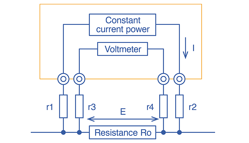 Four-terminal measurement method
There are various types of resistance, including wire, relay, and connector resistance as well as the internal resistance of batteries, so it’s important to use the right instrument for the measurement task at hand. When purchasing an instrument, choose one that suits your purpose.
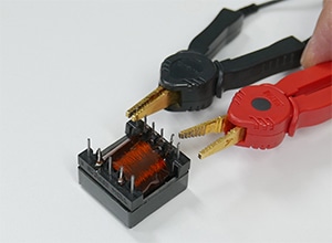 Clip type lead
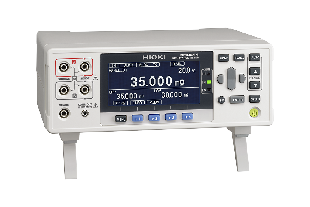
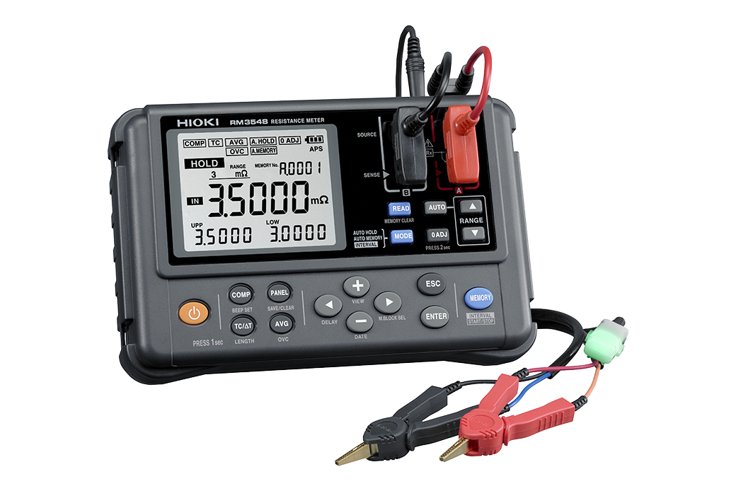
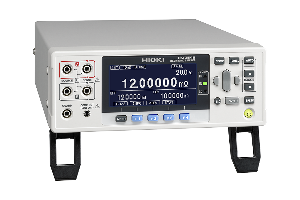
( Clip-type lead for 4-terminal measurement )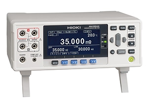 Resistance meters
Sources of error when measuring resistance
Test leads’ wiring resistance is not the only factor that affects resistance value measurement results. The following factors also come into play:
- Electromotive force
- Thermal noise
- Leakage current
- Dielectric absorption
- Friction noise
- External noise
- Temperature, humidity, and wind
Resistance meters provide functionality for reducing the effects of temperature and other factors, for example by reading the difference between a temperature sensor connected to the meter and the reference temperature and correcting resistance values accordingly. If resistance measured values exhibit instability, you’ll need to assess what factors are affecting measurement and take steps to address them.
Rt = Rt0 ×{ 1 + αt0 × (t - t0) }
Rt:Actually tested resistance [Ω]
Rt0:Compensated resistance [Ω]
t0:Reference temperature [°C]
t:Current ambient temperature [°C]
αt0:Temperature coefficient at t0
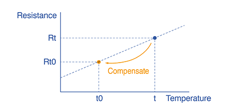
By using a temperature-compensated resistance meter, you can automatically capture the temperature-converted resistance value.
Use a four-terminal resistance meter for more accurate low-resistance measurement
Analog multimeters and digital multimeters use Ohm’s Law to calculate resistance based on current and voltage, rather than measuring resistance itself. Both types of instrument are used in the same basic manner. Digital instruments provide features like four-terminal measurement for greater accuracy.
Resistance values are affected by a variety of external influences. If measurement results exhibit instability, it’s necessary to identify the cause and take steps to address it.