Electric Transformers
What are electric transformers?
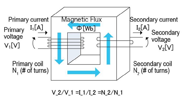
AC voltages can be stepped up or down using a transformer. In terms of their basic structure, transformers consist of primary and secondary windings around an iron core.
When current flows, a magnetic field is generated inside the windings, creating a voltage. The size of this voltage is proportional to the number of turns. For example, a primary winding (on the input side of the transformer) with 100 turns and a secondary winding (on the output side of the transformer) with 200 turns would step up an input voltage of 100 V to an output voltage of 200 V since the number of output turns is twice the number of input turns. Note that there is no change in power between the primary and secondary sides of the transformer.
Setting example of measurement conditions
| Parameters | Ls,Q,Rdc | ||||||||||||||||||
| Frequency | Self-resonant frequency or less *1 | ||||||||||||||||||
| DC bias | OFF(ON is NOT applicable) | ||||||||||||||||||
| Signal level | Rated current or less *1 | ||||||||||||||||||
| Measurement range | AUTO | ||||||||||||||||||
| Speed | SLOW2 | ||||||||||||||||||
| LowZ mode | OFF | ||||||||||||||||||
*The above settings apply to an example measurement. Since optimal conditions vary with the measurement target, specific settings should be determined by the instrument operator.
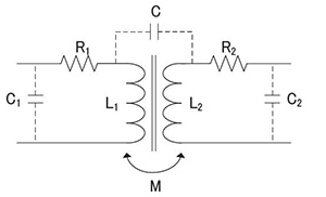
R1: Primary winding
R2: Secondary winding resistance
C1: Primary winding floating capacity
C2: Secondary winding floating capacity
Parameters for each electric transformer
The transformer is an application of an inductor, and measurement methods are the same as for other inductors. Transformer measurement includes the following principal evaluation parameters:
*Primary inductance (L1)and secondary inductance (L2)
*Leakage inductance
*Capacitance between windings (C)
*Mutual inductance (M)
*Turn ratio
Instruments for Mass Production Applications
| Model | Measurement frequency | Features | ||||||||||||||||||||||||||||
| IM3533-01 | DC,1mHz to 200kHz | IM3533+ Frequency sweep | ||||||||||||||||||||||||||||
| IM3536 | DC,4Hz to 8MHz | Standard model, high-speed, highly stable, cost-effective analyzer | ||||||||||||||||||||||||||||
Instruments for Research & Development Applications
| Model | Frequency | Features | ||||||||||||||||||||||||||||
| IM3570 | DC,4Hz to 5MHz | Frequency sweep with analyzer mode | ||||||||||||||||||||||||||||
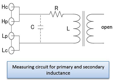
Primary inductance (L1) and secondary inductance (L2)
As shown in the figure, a measuring instrument can be connected directly to the primary or secondary side of the transformer to measure the primary or secondary inductor. However, all other windings must be left in the open state. Exercise care as inductance measurement results include the effects of the winding’s distributed capacitance.
Leakage inductance
In an ideal transformer, shorting output causes input to be shorted as well. However, in an actual transformer, leakage inductance remains even when output is shorted. As shown in the above figure, the leakage inductance can be determined by shorting the secondary side of the transformer and measuring the primary side’s inductance.
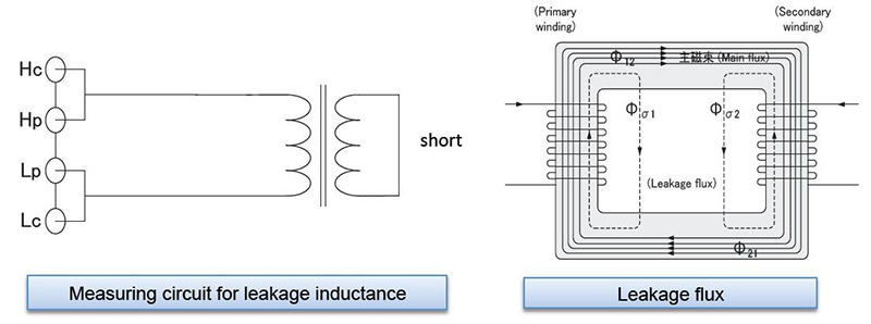
What is leakage inductance?
The magnetic flux that links the transformer’s primary and secondary windings is known as the main magnetic flux (φ12 or φ21). Apart from the main magnetic flux, the transformer’s magnetic flux also includes primary leakage flux (φs1) , which links the primary winding but not the secondary winding, and secondary leakage flux (φs2), which links the secondary winding but not the primary winding.
Although only the main magnetic flux exists in an ideal transformer, actual transformers always have magnetic leakage, and therefore leakage flux. Since this leakage flux does not link only the primary and secondary windings, it does not contribute to the transformer’s voltage-modifying operation. At the same time, the fact that the leakage flux does not link only the primary and secondary windings also means that it contributes as each winding’s inductance. In this way, the primary leakage flux acts as the primary leakage inductance, and the secondary leakage flux acts as the secondary leakage inductance.
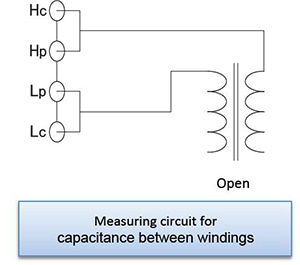
Capacitance between windings
As shown in the figure, the winding capacitance between the primary and secondary sides of the transformer can be measured by connecting each winding to the measuring instrument.
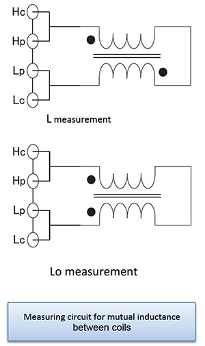
Mutual inductance
The mutual inductance can be calculated by measuring the inductance in parallel while in phase and then in series out of phase and then using the equation shown below.
M=(La-Lo)/4
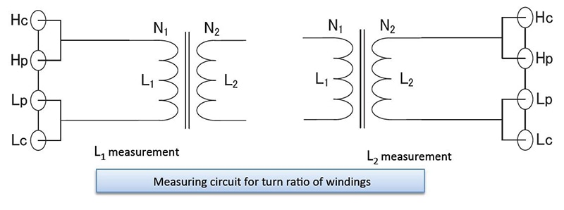
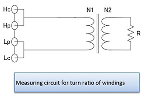
Turn ratio
As shown in the figure, the turn ratio can be approximated by measuring the impedance value Z on the primary side of the transformer after connecting the resistance R to the secondary side.
In addition, the turn ratio can be calculated by measuring the primary inductance L1 and the secondary inductance L2. However, the value will only be an approximation due to the effects of factors such as magnetic leakage.
Transformer measurement functionality
The LCR Meter IM3533/IM3533-01’s transformer measurement functionality can be used to calculate the mutual inductance, turn ratio, and inductance difference.
Turn ratio measurement with the IM3533/IM3533-01 involves measuring the primary and secondary inductance values and then calculating the turn ratio.