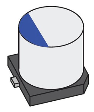
Conductive polymer capacitors
What are conductive polymer capacitors?
Conductive polymer capacitors have lower ESR (see below) than aluminum electrolytic capacitors and are characterized by greater stability with regard to temperature variations. In addition, they offer excellent stability of capacitance relative to DC bias. Measurement conditions are defined by IEC standards 60384-25-1 and include measurements of equivalent series resistance (ESR) and the tangent D (tanδ) of the loss angle.
Setting example of measurement conditions
| Parameters | Cs-D (120Hz), Rs (100kHz) | |||||||||||||||||||||
| Frequency | 120Hz, 100kHz | |||||||||||||||||||||
| DC bias | ON 1.5V | |||||||||||||||||||||
| Signal level | 0.5Vrms | |||||||||||||||||||||
| Measurement range | AUTO | |||||||||||||||||||||
| Speed | SLOW2 | |||||||||||||||||||||
| LowZ mode | ON | |||||||||||||||||||||
* Otherwise, default settings are used.
* The above settings apply to an example measurement. Since optimal conditions vary with the measurement target, specific settings should be determined by the instrument operator.
IEC 60384-25-1 Surface mount fixed aluminium electrolytic capacitors with conductive polymer solid electrolyte
| Parameters | Rated capacitance | Rated voltage | Measurement frequency | Measurement voltage*1 | DC bias *2 | |||||||||||||||||||||||||
| C,D(tanδ) | All | 2.5V or less | 120Hz | 0.5Vrms or less | 1.1 to 1.5V | |||||||||||||||||||||||||
| 2.5V or more | 1.5 to 2.0V | |||||||||||||||||||||||||||||
| Rs(ESR) | All | All | 100kHz±10kHz | 0.5Vrms or less | OFF | |||||||||||||||||||||||||
*1 The measurement voltage (i.e., the voltage applied to the sample) is the voltage obtained by dividing the open-terminal voltage by the output resistance and the sample.
*1 The measurement voltage (i.e., the voltage applied to the sample) can be calculated based on the open-terminal voltage, the output resistance, and the sample’s impedance.
*2 DC bias need not be applied.
Low impedance high accuracy mode settings
Low impedance high accuracy mode
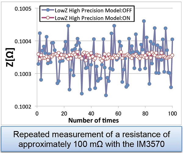
In low impedance high accuracy mode, the instrument’s output resistance is reduced, and the measurement current is applied repeatedly for increased measurement precision. When measuring a capacitor with a high capacitance of greater than 100μF (and therefore low impedance), low-impedance high-precision mode yields more stable measurement. The graph on the right compares repeatability when using the IM3570 to make measurements with low-impedance high-precision mode enabled and disabled (100kHz, 1Ω range, 1V).
*The conditions under which low-impedance high-precision mode can be enabled vary with the instrument model. Please refer to the user’s manual of the instrument you are using.
Instruments for Mass Production Applications
| Model | Measurement frequency | Features | ||||||||||||||||||||||||||||
| IM3523 | DC, 40Hz to 200kHz | Measurement time: 2ms, high cost performance | ||||||||||||||||||||||||||||
| IM3533 | DC, 1mHz to 200kHz | Internal DC bias function, touch panel | ||||||||||||||||||||||||||||
Instruments for Research & Development Applications
| Model | Measurement frequency | Features | ||||||||||||||||||||||||||||
| IM3570 IM9000 | DC, 4Hz to 5MHz | Frequency sweep with analyzer mode | ||||||||||||||||||||||||||||
| IM3570 | ||||||||||||||||||||||||||||||
| IM3590 | DC, 1mHz to 200kHz | Can measure ESR and ESL separately with its equivalent circuit analysis function. | ||||||||||||||||||||||||||||
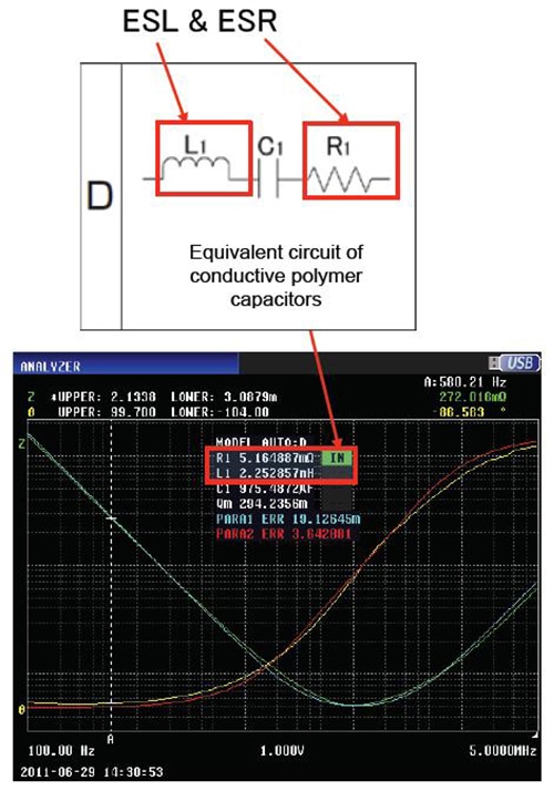
Equivalent circuit analysis function
The instrument’s equivalent circuit analysis function can be used to analyze the L, C, and R elements that make up the component separately. In the figure on the right, a conductive polymer capacitor’s ESR and ESL are measured using the IM3570 and IM9000.
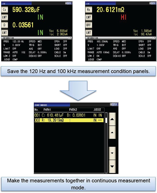
Continuous measurement mode
The IM35xx series’ continuous measurement mode can be used to make continuous measurements while varying settings (frequency and level). In the example on the right, continuous Cs-D (120 Hz) and ESR (100 kHz) measurements are performed.