Performing zero-adjustment
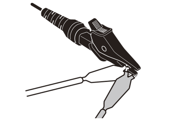
Connect the black measurement cord to the E terminal, the yellow measurement cord to the S (P) terminal, and the red measurement cord to the H (C) terminal and short the tips of the three measurement cords as shown in the figure below.
Then operate the ground resistance tester to perform zero-adjustment.
Connecting the measurement cords
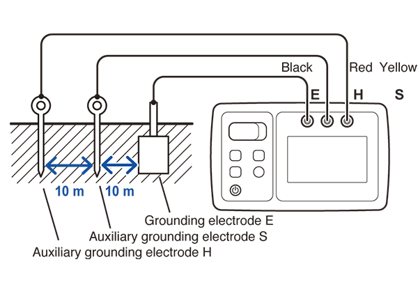
Connect the grounding electrode and the E terminal with the black measurement cord.
Carrying the two reels, move to the measurement location while paying out the measurement cords. Insert an auxiliary grounding electrode into the ground once all of the yellow measurement cord has been paid out and connect the yellow measurement cord to the electrode.
Reposition yourself by walking along the straight line connecting grounding electrode E and the auxiliary grounding electrode S while paying out the red measurement cord from its reel.
Insert another auxiliary grounding electrode into the ground once all of the red measurement cord has paid out and connect the red measurement cord to the electrode.
Measuring the ground resistance
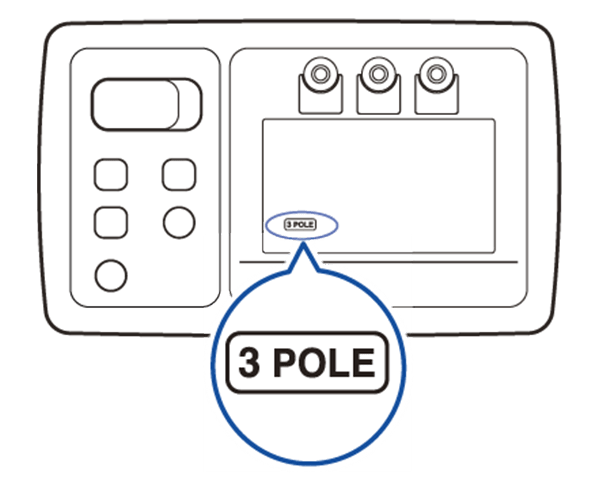
Press the power button to turn on the instrument. Then press the Fn button to display “3 POLE.” The ground potential will be displayed.
Pressing the MEASURE button will cause the instrument to automatically check the ground potential, check the auxiliary ground resistance, and measure the ground resistance.
Measurement will complete in about 8 seconds, and the instrument’s display will light up and show the measured value. Check the measured value.
Measuring ground resistance on concrete
Since concrete is a conductor, it is possible to place the auxiliary grounding electrodes on concrete.
Place the auxiliary grounding electrode on the concrete and pour some water over it, or place a wet cloth on top of the auxiliary grounding electrode.
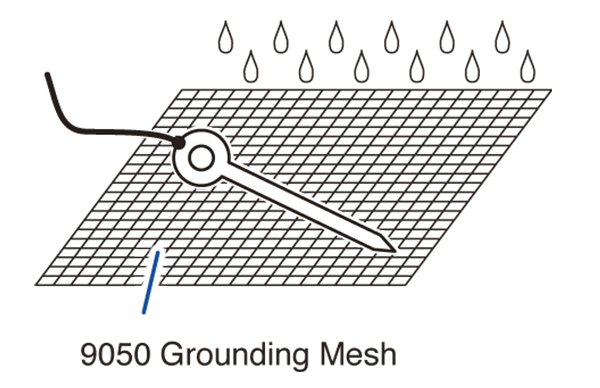
If this method fails to lower the auxiliary grounding electrode’s ground resistance, spread the optional 9050 Grounding Mesh on the concrete, place the auxiliary grounding electrode on top of the grounding mesh, and then pour water over both. Allow the water to soak into the concrete before measuring the resistance. An object such as a metal plate or a sheet of aluminum foil can be used as a substitute for the grounding mesh. However, the grounding mesh is more effective at lowering the auxiliary grounding electrode’s ground resistance.
Since asphalt is an insulator, it is not generally possible to place auxiliary grounding electrodes on asphalt. However, water-moistened asphalt may permit measurement in some cases.