Impedance Measurement of Reactors While in Operation
Why Should A Reactor’s Impedance Be Measured?
Reactors often serve to protect both motors and variable
frequency drives (VFDs) from harmful current and
voltage spikes by slowing the rate of
current changes in the line via the applied impedance. They also aid in reducing power
line distortion, known as harmonics, by adding
impedance to the power system.
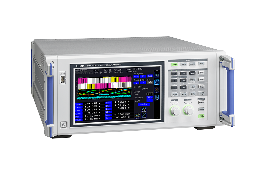
By identifying the impedance of a reactor while it is in operation, you can gain indices that aid in circuit design. Because there is a level dependency in reactor impedance, values measured by an LCR meter differ from the actual value when the reactor is in operation. By using a Power Analyzer to measure impedance while a reactor is in operation, you can capture the true impedance value.
How is Impedance Measured?
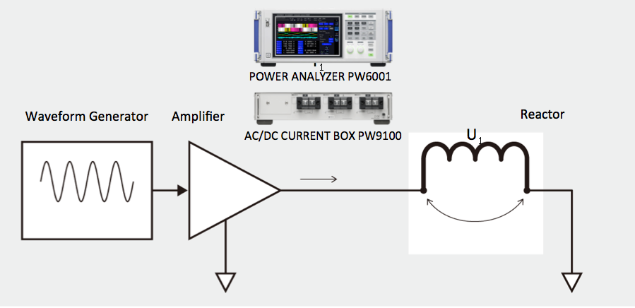
High frequency current is applied to the reactor. The Power Analyzer then measures the reactor voltage, current, and phase difference. Using the measurement results, we can then measure impedance, inductance and resistance components.

Measureable Parameters
- Reactor Inductance Z and Phase Difference θ can be derived from U1 and I1.
- Inductance Ls and Resistance Component Rs can be derived from Inductance Z and Phase Difference θ.
Key Benefits of Power Analyzers
- Thanks to the wide frequency bandwidth and phase shift correction function, the amplitude and phase of high frequency voltage and currents on reactors, capacitors, and similar devices can be accurately measured.
- Based on the customer’s own defined formulas, display the parameters associated with the impedance of circuit elements on the Power Analyzer in real time.
- With the X-Y Plot Function, display the correlations between multiple parameters in a frequency characteristics graph or similar tool on the Power Analyzer in real time.


