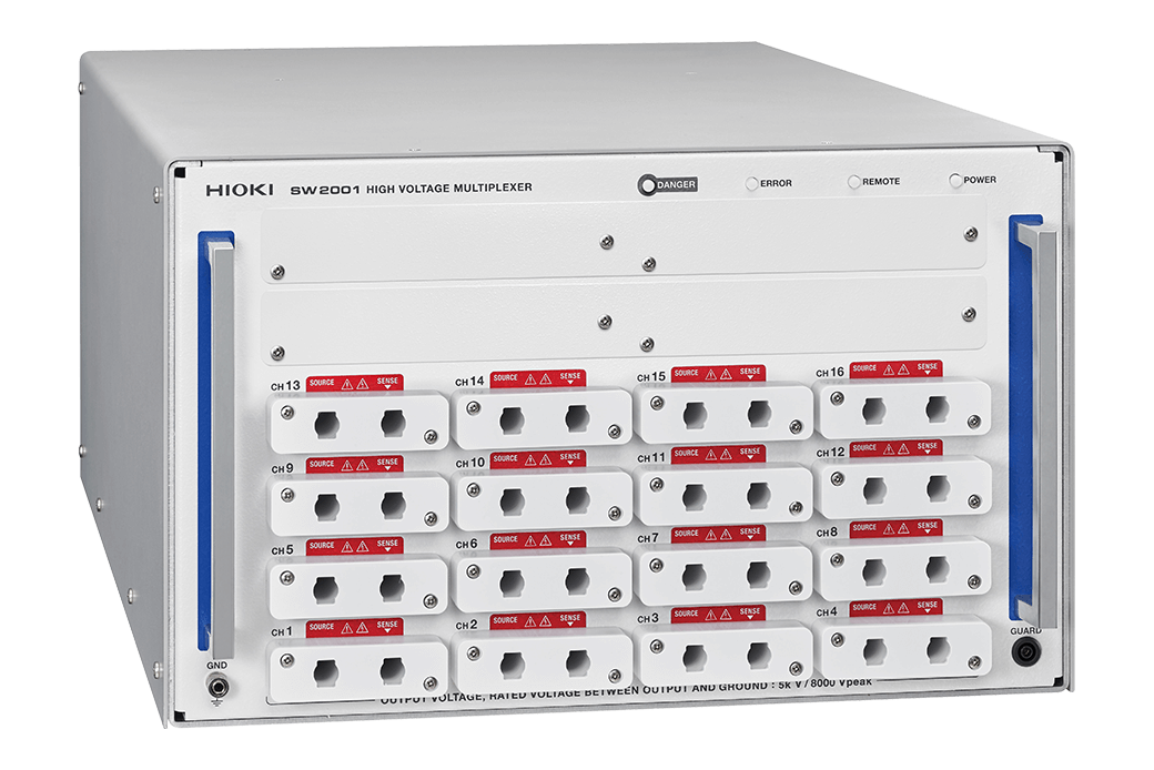
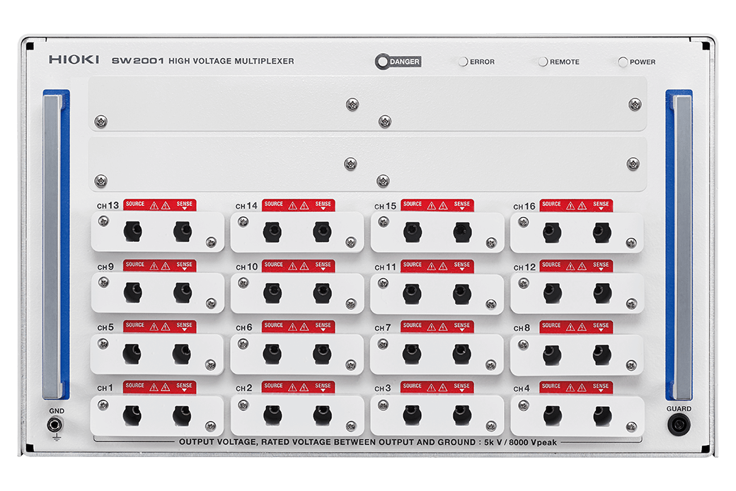
HIGH VOLTAGE MULTIPLEXER SW2001
Durable multiplexer for comprehensive motor testing systems
Ideal for building systems that combine high-voltage testing and 4-terminal low-voltage measurement
The SW2001 High Voltage Multiplexer is designed to connect multiple testers for six different tests, allowing safe and seamless switching between high-voltage and 4-terminal low-voltage testing. (It is designed to connect testers for the winding resistance test, inductance test, insulation resistance test, hipot test, surge test, and partial discharge test [AC PD and Surge PD].)
The multiplexer minimizes risk of damage to low-voltage test equipment by effectively mitigating the impact of stored energy in windings during high voltage testing such as hipot tests and insulation resistance tests. The robust multiplexing design ensures measurement accuracy and reduces the need for frequent replacements of high-voltage relays.
Key Features
- A single multiplexer that lets you consolidate six different tests
- Safe switching between high-voltage testing and 4-terminal low-voltage measurement
- Reliable multiplexing design with extended operational lifespan
- Guaranteed measurement performance and high durability
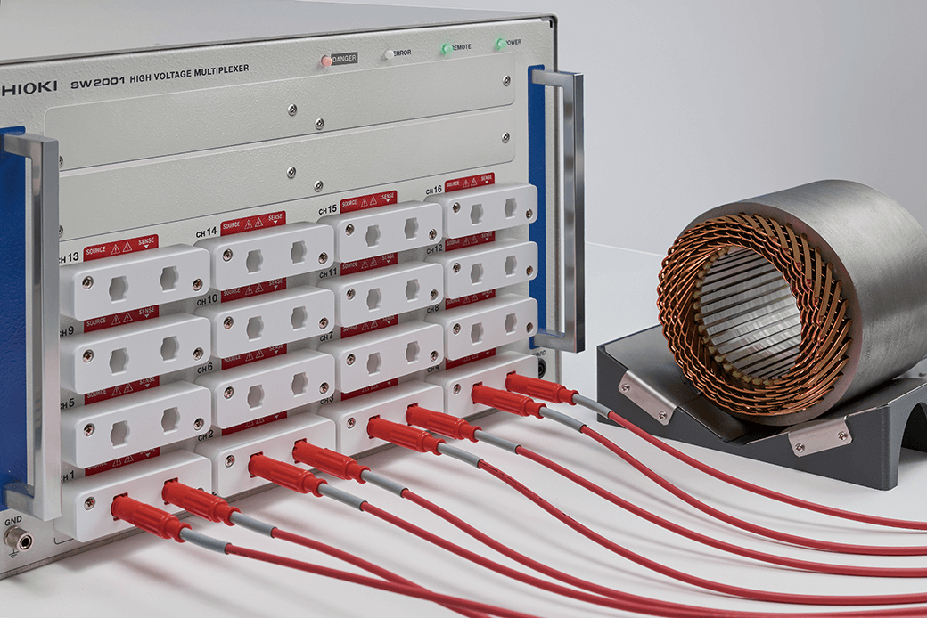
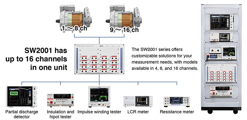
- Up to 16 channels significantly reduce connection man-hours and test time
Model No. (Order Code)
| SW2001-04 | 4 ch |
|---|---|
| SW2001-08 | 8 ch |
| SW2001-16 | 16 ch |
Boost efficiency with one multiplexer handling six tests
Select the number of channels based on your testing needs: 4, 8, or 16 channels
Streamline your motor inspections by connecting multiple instruments for six different tests: resistance, inductance, surge, hipot, insulation resistance, and partial discharge (AC PD and surge PD). The multiplexer eliminates the need for frequent reconnections, in both serial motor test lines (conventional test lines) and parallel motor test lines. The SW2001 supports simultaneous testing of up to 3 three phase motors with two built-in thermistor temperature sensors.
Enhance reliability with reduced production line stops, test accuracy, and reproducible results
Highly reliable multiplexing design with extended operational lifespan
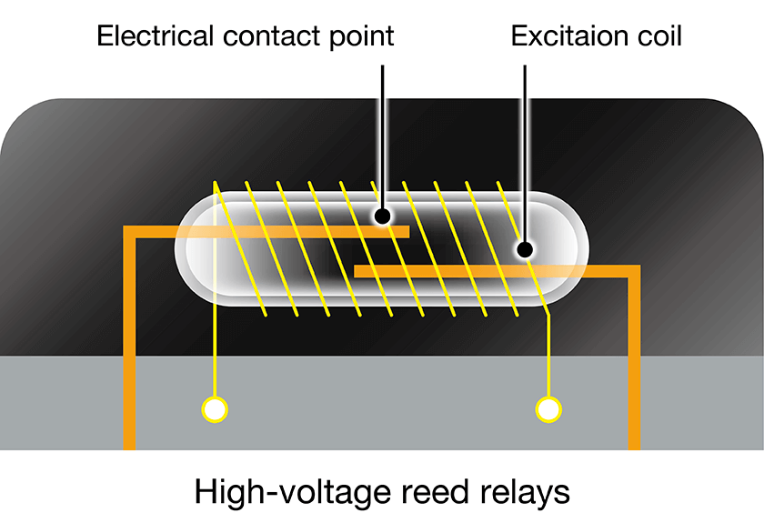
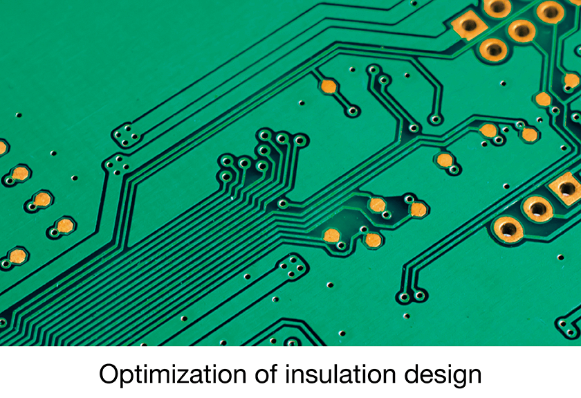
The SW2001 employs highly durable high-voltage reed relays to reduce maintenance frequency. These relays operate by generating a magnetic field through current flow in an adjacent excitation coil, which switches the contacts inside a glass tube. The multiplexer’s high-voltage reed relays with this operating mechanism enable safe switching in high-voltage circuits (with a maximum peak voltage of 8 kV) and help reduce the impact of leakage current on measurements. In addition to adopting such reed relays, the SW2001 multiplexer utilizes advanced insulation design to Electrical contact point Excitation coil ensure more accurate measurements. This includes optimizing the spatial insulation distance between relays, selecting appropriate insulation materials, and using high-voltage printed circuit boards to enhance insulation between relays and grounding. Furthermore, to minimize the risk of damage to the measuring instrument caused by energy accumulated in the measured winding, a protective discharge function is incorporated.
Guaranteed measurement performance and high durability
Effect of on accuracy
- Insulation resistance measurement accuracy: 2% (1 MΩ to 1 GΩ)
- Magnitude of effect on AC PD measurement: 40 pC or less (during 3 kV application)
Durability
- Maximum allowable impulse current: 100 A peak
- Main circuit relay service life: 5 million or more cycles (reference value, not guaranteed)
Reliable switching
The SW2001 facilitates safe and precise measurement for the diverse set of motor tests that demand a wide range of specs from high sensitivity for low voltages (motor winding resistance tests and inductance tests) to high-voltage resistance (max. 5 kV RMS for AC/ DC hipot tests and max. 8 kV peak for surge tests).
Preventing damage to low-voltage meters from stored energy
The protective discharge function can ground the output-side main circuit so that it can discharge residual energy prior to closing the I/O relay's main circuit.
Basic specifications
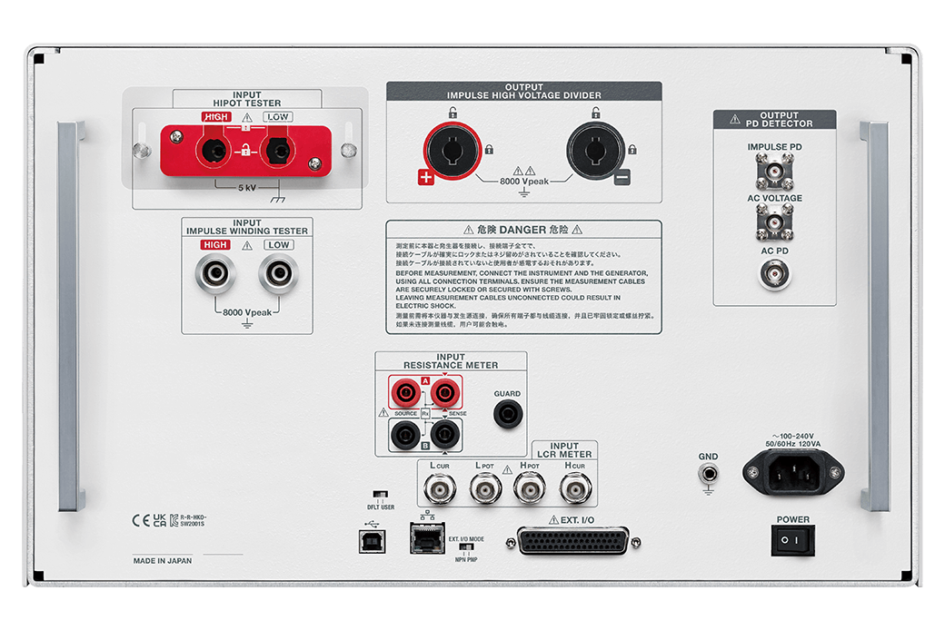
| Input channels | 2 channels of high-voltage, 2-terminal input: insulation and withstanding voltage tester input, impulse winding tester input 2 channels of low-voltage, 4-terminal input: LCR meter input, resistance meter input |
|---|---|
| Output channels | CH1 to CH4 (SW2001-04), CH1 to CH8 (SW2001-08), CH1 to CH16 (SW2001-16) SOURCE terminal (or 2-terminal output terminals) and SENSE terminal for each channel |
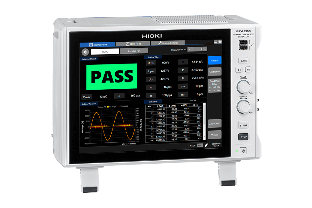
| Partial discharge sensor output | AC voltage monitoring, AC partial discharge current, impulse partial discharge current (Current output is available only when equipped with current sensor ST9200 or ST9201-50 which are options that must be specified when ordering.) (Each is output through a BNC terminal.) |
| Maximum input voltage | High-voltage two-terminal input HIPOT (HIPOT TESTER terminal): 5 kV AC rms, 5 kV DC, 7.07 kV peak High-voltage two-terminal input IMPULSE (IMPULSE WINDING TESTER terminal): 8 kV peak (impulse) Low-voltage four-terminal input LCR and RESISTANCE: 30 V AC rms, 60 V DC, 42.4 V peak |
| Rated output voltage | Output channel: 5 kV AC rms, 5 kV DC, 8 kV peak (impulse) Impulse high voltage divider output (IMPULSE HIGH VOLTAGE DIVIDER output terminal): 8 kV peak (impulse) |
| Maximum rated terminal-to-ground voltage |
High-voltage two-terminal input HIPOT (HIPOT TESTER terminal): 5 kV AC rms, 5 kV DC, 7.07 kV peak High-voltage two-terminal input IMPULSE (IMPULSE WINDING TESTER terminal): 8 kV peak (impulse) Low-voltage four-terminal input LCR and RESISTANCE: 30 V AC rms, 60 V DC, 42.4 V peak Output channel: 5 kV AC rms, 5 kV DC, 8 kV peak (impulse) Impulse high voltage divider output (IMPULSE HIGH VOLTAGE DIVIDER output terminal): 8 kV peak (impulse) |
| Maximum allowable impulse current | 100 A peak |
| Primary circuit relay service life | Open/close cycles: 5 million or more (reference value, not guaranteed) |
General specifications
| Functions | Channel switching, interlock, channel delay, settings backup, panel function, communications settings mode switching, protective discharge function, accelerated discharge function |
|---|---|
| Interfaces | LAN, USB, EXT. I/O |
| Power supply | Rated supply voltage: 100 to 240 V AC Rated power: 120 VA |
| External dimensions | Approx. 439.2 mm (17.29 in.) W × 265.9 mm (10.47 in.) H × 770 mm (30.31 in.) D (excluding protruding parts) |
| Weight | SW2001-04: approx. 20.5 kg (723.1 oz.); SW2001-08: approx. 22.5 kg (793.7 oz.); SW2001-16: approx. 27.0 kg (952.4 oz.) (All figures do not include weight from factory options ST9200/ST9201-50.) Add 1.2 kg (42.3 oz.) for each ST9200 and add 0.32 kg (11.29 oz.) for each ST9201-50. |
| Included accessories | Power cord × 1, operating precautions × 1, startup guide × 1, support feet for installation × 4, EXT I/O connector × 1, connector for disengaging EXT I/O interlock × 1 |
Partial discharge sensor (2)
Please specify at time of order as the following components are embedded during the manufacturing process.

For AC partial discharge detection
Specify at time of order; built into SW2001
For surge partial discharge detection
Specify at time of order; built into SW2001
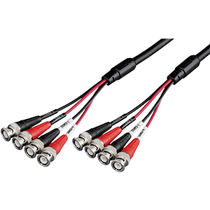
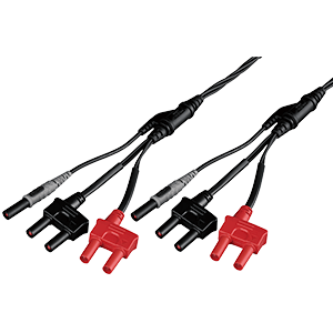
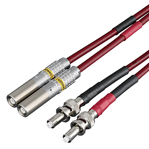
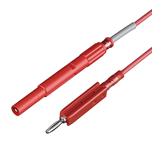
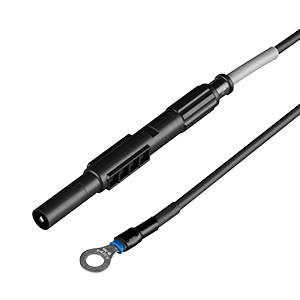
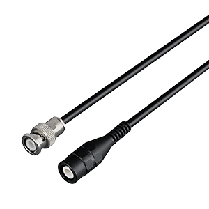
Connection cables (8)

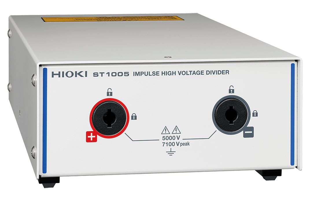
Red and black set: For connecting ST1005 to SW2001, 1.5 m
4-terminal: For connecting the IM3533, 1.5 m
4-terminal: For connecting the RM3545, 1.5 m
Red and black set: For connecting the ST4030A, 1.5 m
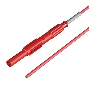
Red, 3 m
Red Hi: For connecting the 3153, 1.5 m
Black Low: For connecting the 3153, 1.5 m
For connecting the ST4200 and SW2001, 1.5 m
Communication cable (1)
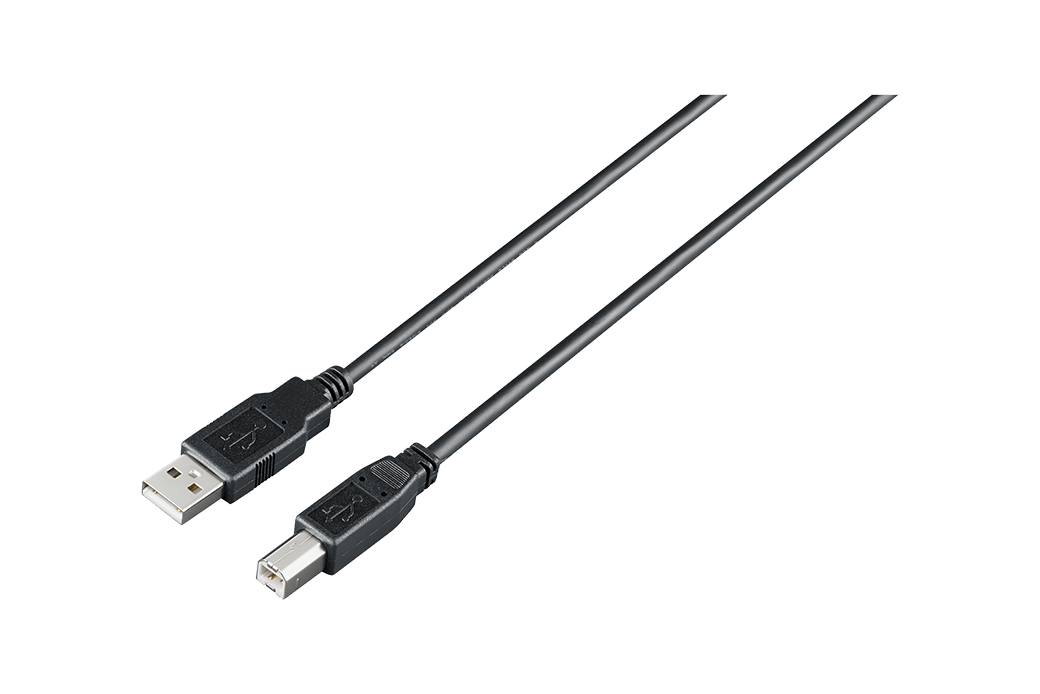
1 m
-
PARTIAL DISCHARGE DETECTOR ST4200-50, HIGH VOLTAGE MULTIPLEXER SW2001-04, SW2001-08, SW2001-16
 Startup Guide
Simplified Chinese
Ver.01
Startup Guide
Simplified Chinese
Ver.01
-
HIGH VOLTAGE MULTIPLEXER SW2001-04, SW2001-08, SW2001-16
Instruction Manual
Simplified Chinese
Ver.02
-
HIGH VOLTAGE MULTIPLEXER SW2001-04, SW2001-08, SW2001-16
Instruction Manual
English
Ver.02
-
PARTIAL DISCHARGE DETECTOR ST4200-50, HIGH VOLTAGE MULTIPLEXER SW2001-04, SW2001-08, SW2001-16
Startup Guide
English
Ver.01