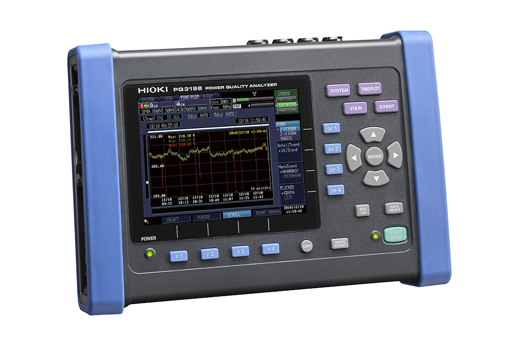
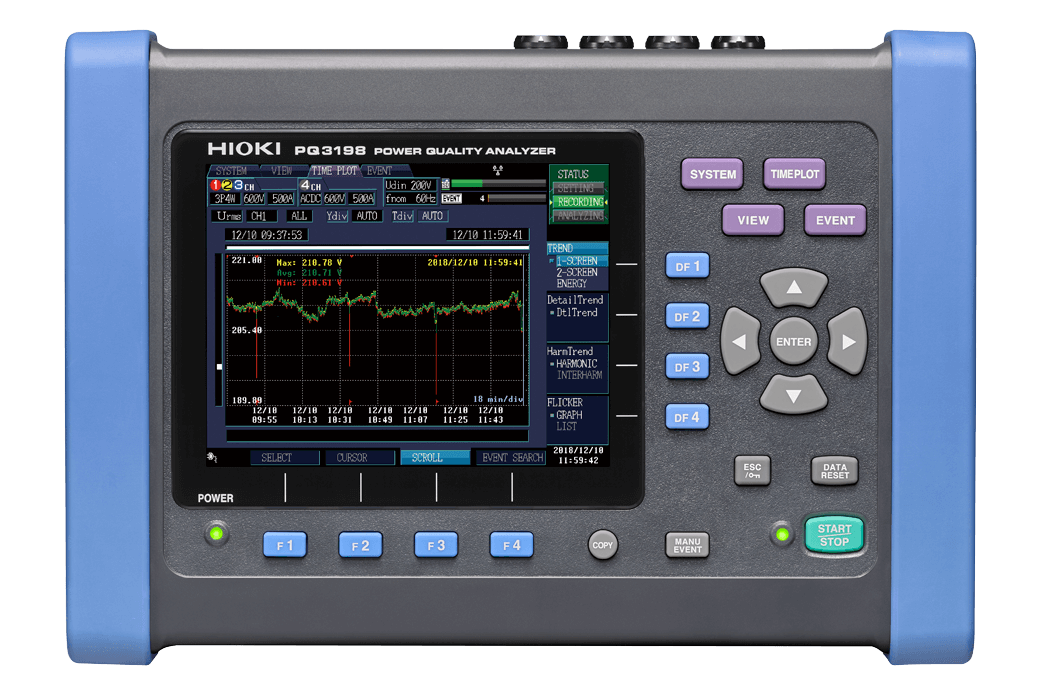
POWER QUALITY ANALYZER PQ3198
Investigate Power Characteristics and Analyze the Causes of Problems
Hioki portable power meters and analyzers are best in class power measuring instruments for measuring single to three-phase lines with a high degree of precision and accuracy. The new and improved PQ3198 is a power quality analyzer for monitoring and recording power supply anomalies, allowing their causes to be quickly investigated, and also for assessing power supply problems such as voltage drops, flicker, harmonics, and other electrical issues. New features include the ability to drive current sensors straight from the PQA and enhanced recording capabilities.
Key Features
- Verify power problems in accordance with the IEC61000-4-30 Edition 3 Class A standard
- High accuracy and continuous gapless recording
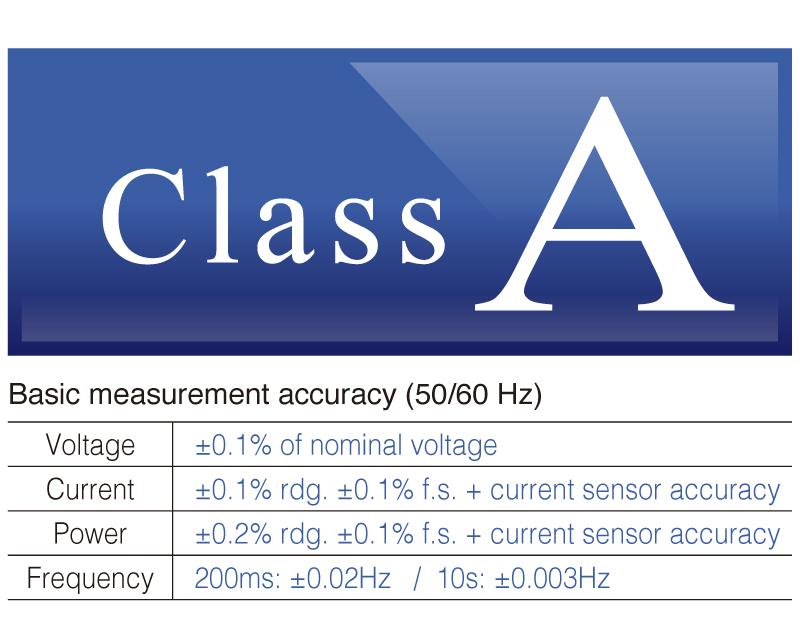
(V: ±0.1% of nominal voltage, A: ±0.1% rdg. ±0.1% f.s., W: ±0.2% rdg. ±0.1% f.s.)
- Broadband voltage range lets you measure even high-order harmonic (supraharmonic) components of up to 80 kHz
- Maximum 6000 V peak transient voltage up to 700 kHz
- Measure up to 6000 A AC
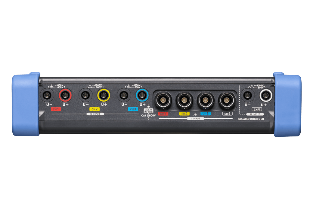
- Two systems of power measurement and efficiency calculation for (ch 1, ch 2, ch 3) and ch 4
- IEEE 519 Compliance harmonics measurement
- Easily create reports with bundled PQ ONE application software
- Optional GPS BOX for synchronizing multiple devices
Model No. (Order Code)
| PQ3198 | Main unit, current sensor is sold separately |
|---|---|
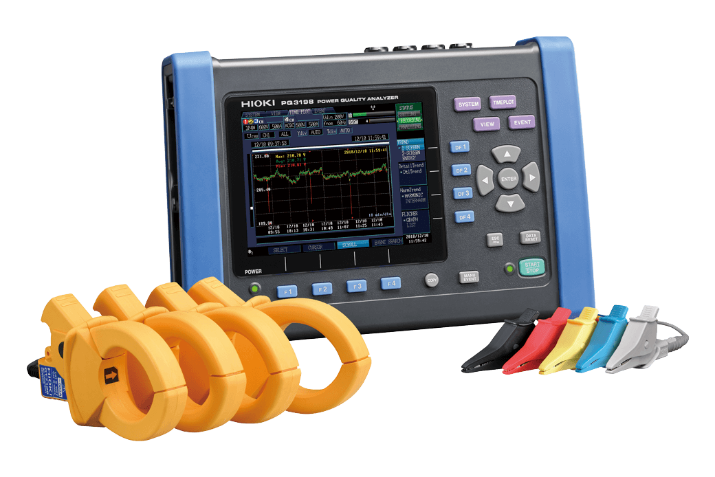
| PQ3198-92 | Kit includes 600 A sensor × 4 and other options |
| PQ3198-94 | Kit includes 6000 A sensor × 4 and other options |
Power quality monitoring, troubleshooting, and energy management
Logging and waveform recording
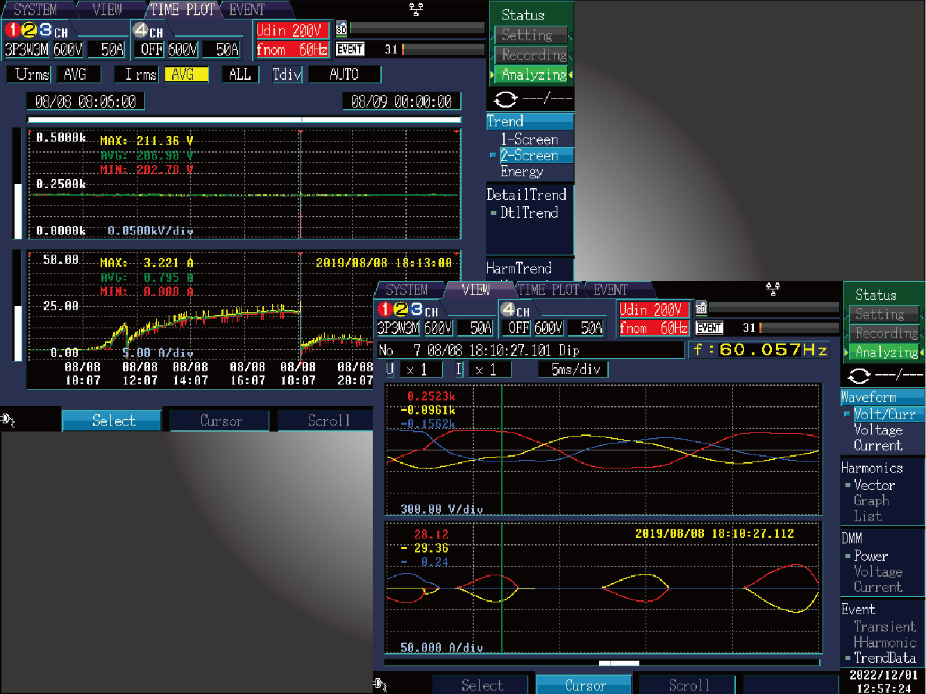
The PQ3198 is a three-phase power quality analyzer that allows simultaneous power logging and waveform capture of power quality anomalies (events).
Record up to 9999 power quality anomalies (events) and trend data up to 1 year.
Easy to Set up
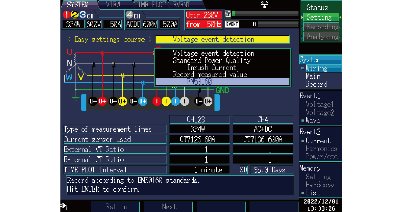
Preset
Simply choose the preset that suits your application, and the instrument will automatically configure the recording parameters.
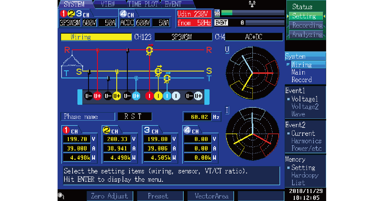
Wiring and connection guide
The instrument will perform an automatic wiring check and display the results.
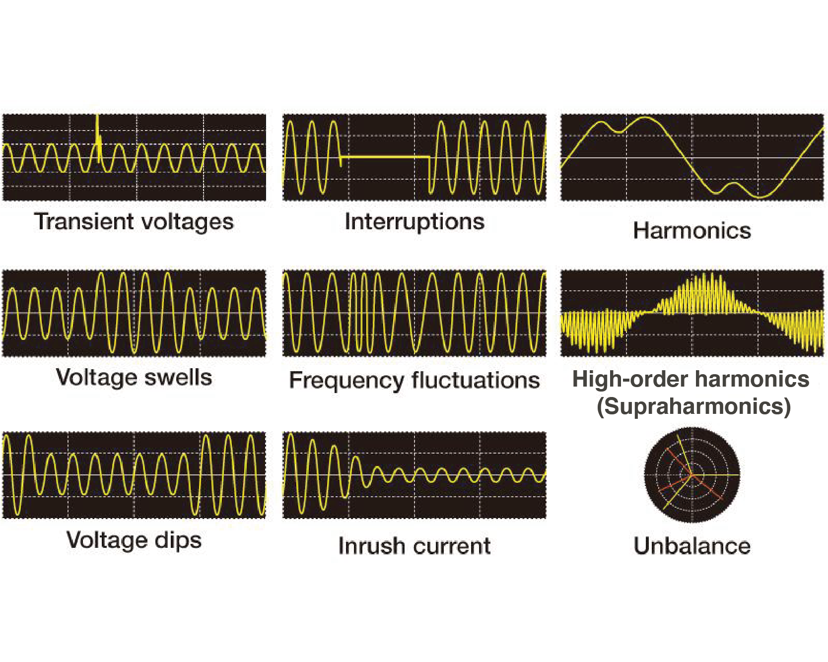
Capture power anomalies reliably with simple settings
The PQ3198 can measure all parameters at once, including power,
harmonics, and anomaly waveforms.
Transient voltages
Voltage swells
Voltage dips
Interruptions
Frequency fluctuations
Inrush current
Harmonics
High-order harmonics (Supraharmonics)
Unbalance
Standard compliant
IEC 61000-4-30 Ed. 3 Class A compliant
The PQ3198 complies with the IEC 61000-4-30 Ed. 3 Class A standard.
As a result, it can perform standard-mandated measurement tasks such as gapless,
continuous calculation; detection of events such as swells, dips, and interruptions;
and time synchronization using GPS (optional).
Class A
Part of the IEC 61000-4-30 international standard, Class A defines power quality parameters, accuracy, and standard compliance to facilitate the comparison and discussion of measurement results from different instruments.
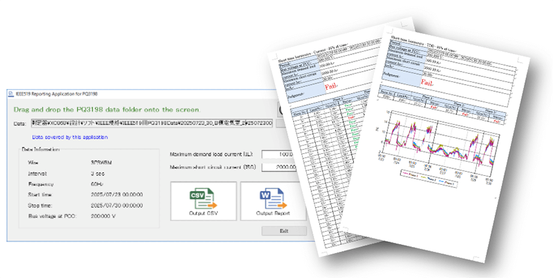
IEEE 519 Compliance harmonics measurement
Free software for creating harmonic measurement reports required by the international standard IEEE 519.
Select report items from Very Short Time (3 seconds), Short Time (10 minutes) harmonics, TDD, and THD.
EN50160 judgment function (PQ ONE)
Evaluate whether data complies with the EN 50160 standard by analyzing it and generating a judgment based on voltage fluctuations during the trend interval. You can also customize the judgment criteria and parameters. The IEEE 519 TDD and GB Power Quality Statistics Report are also available.
Two-circuit measurement
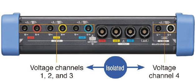
Since the PQ3198's fourth voltage channel is isolated from its first three voltage channels, the instrument can measure power and efficiency across two separate circuits.
Simple inverter measurement
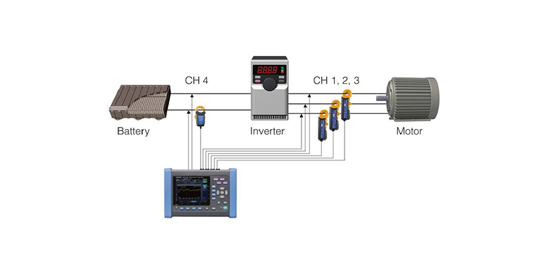
The PQ3198 can measure the secondary side of inverters with a fundamental frequency of 40 to 70 Hz and a carrier frequency of up to 20 kHz.It can also measure the efficiency of DC/3-phase inverters.
Verify the quality of power supplied by an EV rapid charger

Verify the quality of the input (AC) and output (DC) of an EV rapid charger while simultaneously measuring power and efficiency between input and output.
- *For more precise inverter measurement, HIOKI recommends the POWER ANALYZER
Other features
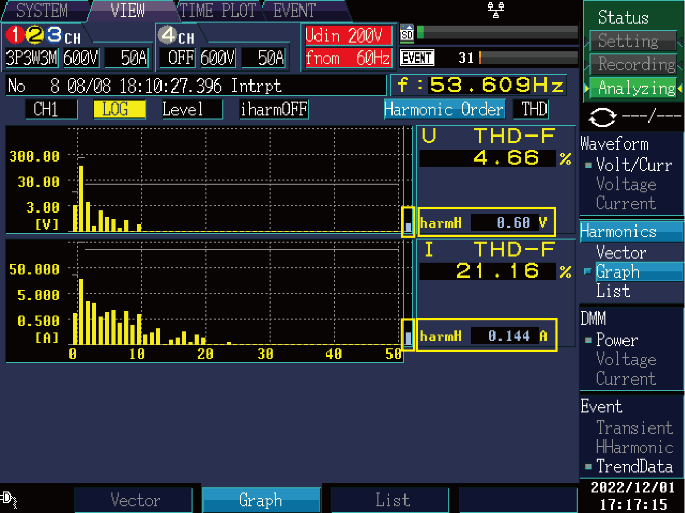
High-order harmonic (supraharmonic) measurement
The high-order harmonic (supraharmonic) component consists of noise components of several kHz or more caused by voltage and current waveform distortions when equipment power supplies use semiconductor devices. It includes various frequency components.
The PQ3198 can measure high-order harmonics (supraharmonics) components from 2 kHz to 80 kHz.
High-speed transient measurement
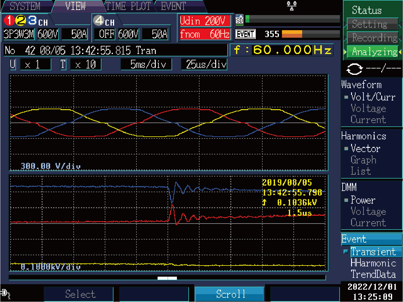
Transient voltage occurs due to phenomena such as lightning, breaker damage, or the closure of the circuit breaker or relay. It often occurs when there is a radical change in voltage or when the peak voltage is high.
The PQ3198 can measure transient voltages of up to 6000 V lasting as little as 0.5 μs (2 MS/s).
400 Hz line measurement
Power measurement for aviation systems and shipboard systems. In addition to 50/60 Hz, the PQ3198 can measure a line frequency of 400 Hz.

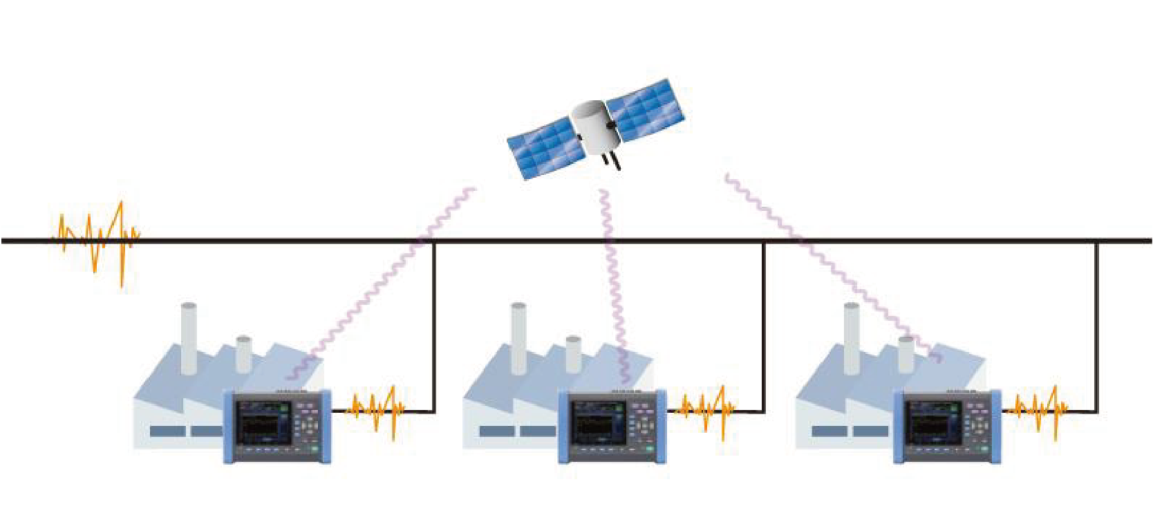
GPS time synchronization
The GPS OPTION PW9005 can be used to correct the instrument's internal time to UTC standard time. This capability eliminates any time difference between instruments to allow analysis that preserves the simultaneity of phenomena measured with multiple instruments.
Intuitive software for data analysis and report creation
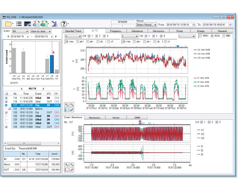
Analyze data and generate reports with HIOKI’s PQ ONE power quality analysis software
Group data from different measurement locations, times, and dates into folders and view them together.
Display detailed measurement data, including event statistics, an event list, and event graphs. Simply choose the parameters you need to output to the report.
Output CSV and PQDIF format files for the parameters you choose. PQDIF format files can also be uploaded to the software.
Statistics display function
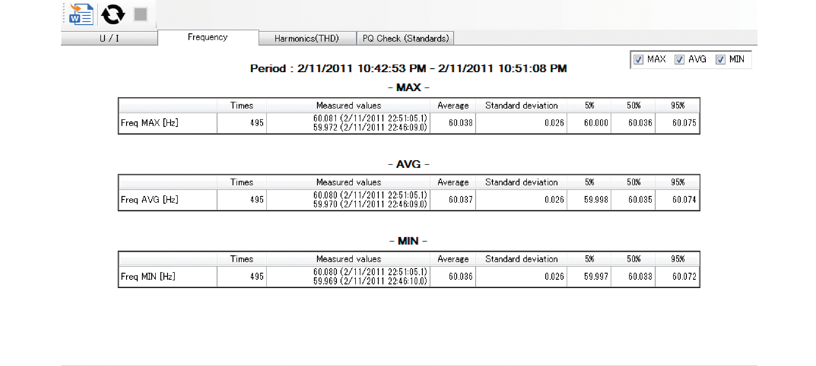
Show voltage, current, frequency, harmonics, flicker, and other metrics on the Statistics screen. View the maximum, minimum, and average value for measurement data context.
ITIC curve
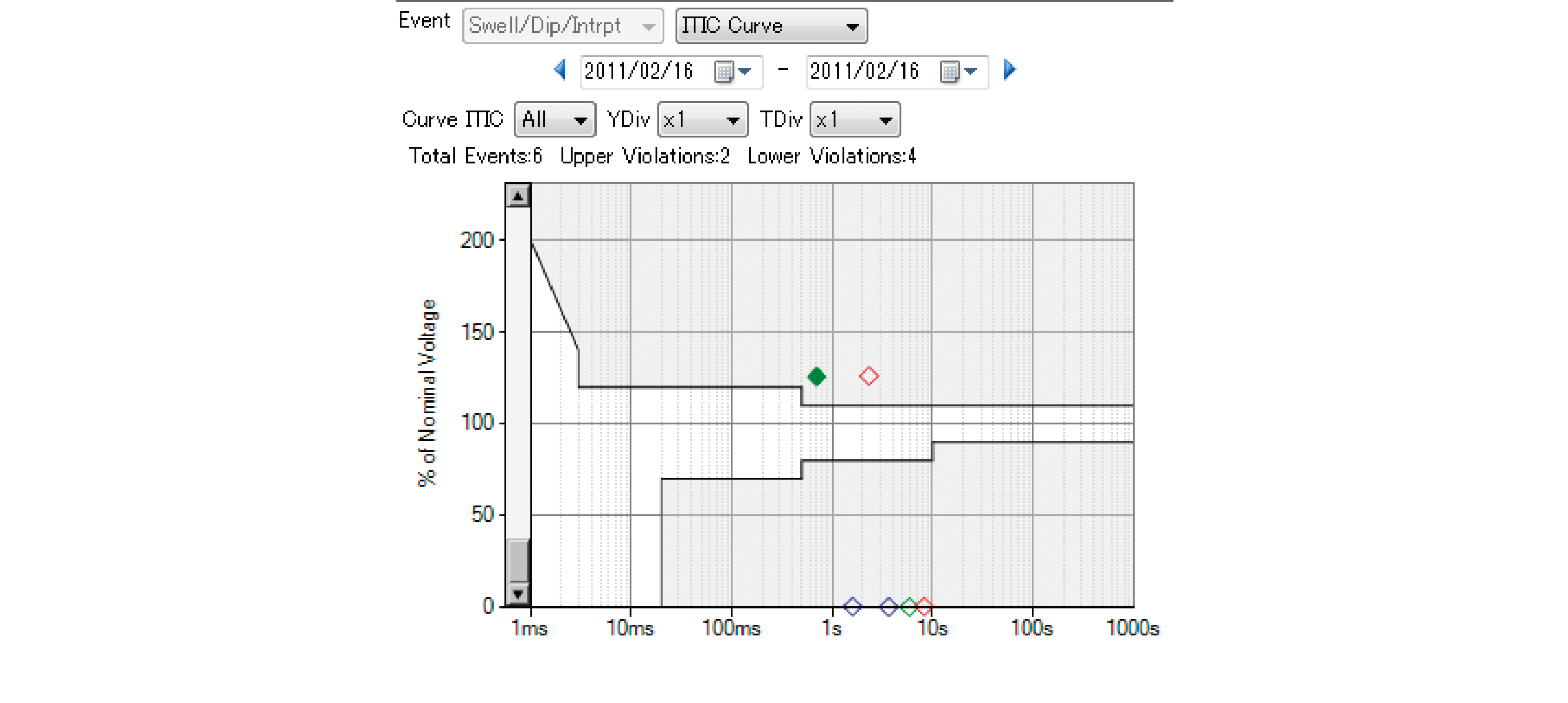
Automatically generate ITIC curve from recorded event. The curve estimates IT equipment's resistance to power quality issues such voltage fluctuations.
Remote measurement
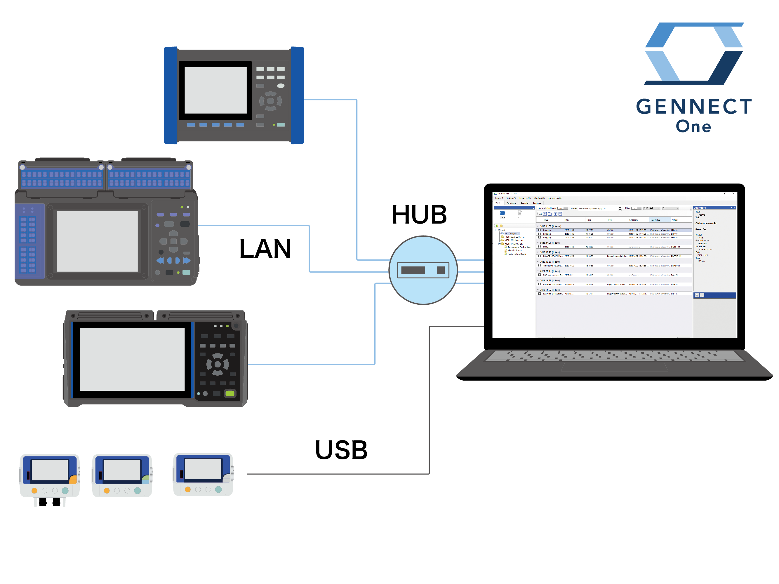
Remote Monitoring of a Site’s Power Supply Quality [GENNECT One SF4000]
Get measurement results from the job site in real-time, and display/save them on your PC.
Immediately and automatically transfer power supply quality event measurement files to your PC.
The power quality analyzer itself can be remotely controlled from your PC to change event conditions.
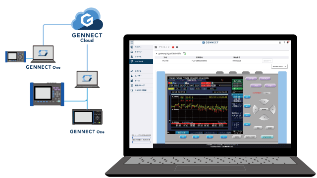
Escape from your LAN! Realize genuinely remote measurement
Use GENNECT cloud, a cloud service operated by Hioki specifically for its GENNECT line of services, to realize genuinely remote measurement. Acquire measured values in real time, collect data, and control instruments via the cloud, anytime, from anywhere.
Wide range of sensors for better quality measurement
Wide array of ranges to accommodate all applications
Use HIOKI sensors in an array of applications to measure equipment ranging from the secondary side of CTs to high-current wiring.
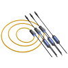
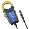
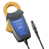
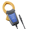
The CT7136 offers three ranges (50 A/500 A), as do HIOKI's flexible sensors (50 A/500 A/5000 A).
Since the effective measurement range extends to 120% of the nominal range,
flexible sensors can be used to measure currents of up to 6000 A.
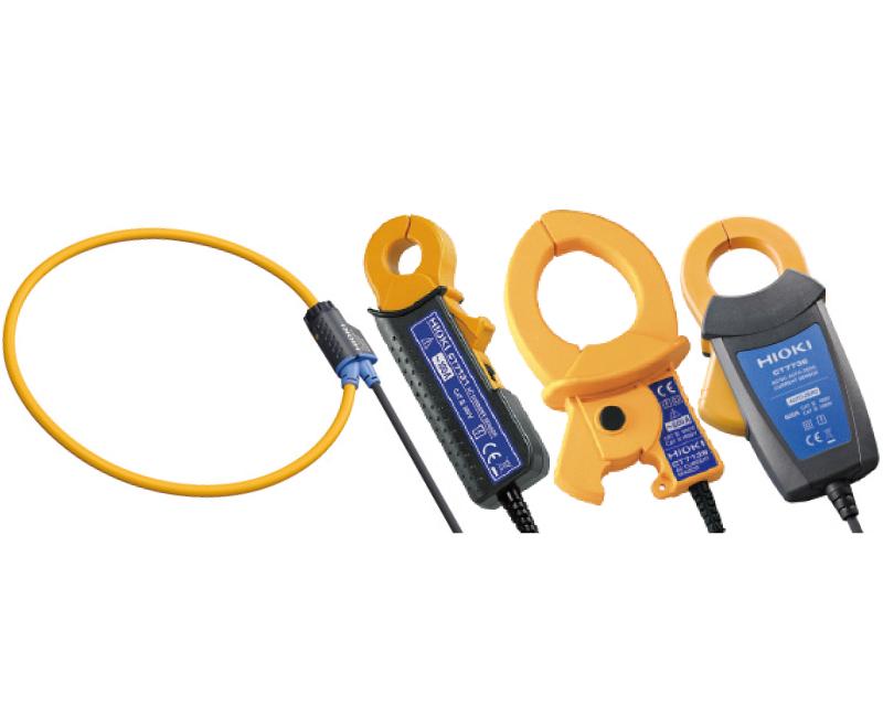
No need for an external power supply
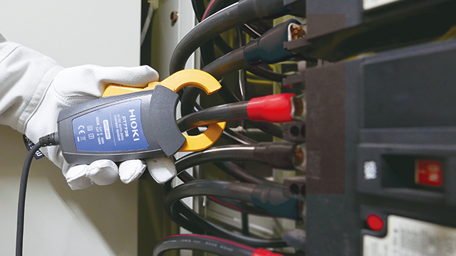
AC/DC auto-zero current sensors measure DC current accurately over extended periods of time,eliminating the need to concern yourself with zero-point drift. Since sensor power is supplied by the instrument, there's no need for an AC adapter when using AC/DC sensors or flexible sensors.
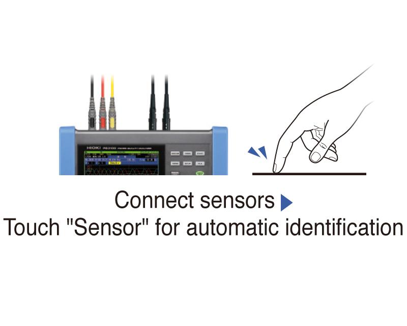
Automatic sensor detection to avoid erroneous measurement
Simply connect current sensors, touch "Sensor" on the screen, and the instrument will automatically detect sensor types and maximum current ranges.
Basic specifications (Accuracy guaranteed for 1 year, Post-adjustment accuracy guaranteed for 1 year)
| Measurement line type | Single-phase 2-wire, Single-phase 3-wire, Three-phase 3-wire or Three-phase 4-wire plus one extra input channel for voltage, current, power measurement (AC or DC measurement) | |||||
|---|---|---|---|---|---|---|
| Voltage ranges | Voltage measurement: 600.00 V rms Transient measurement 6.0000 kV peak |
|||||
| Current ranges | 500.00 mA to 5.0000 kA AC (depends on current sensor in use) | |||||
| Power ranges | 300.00 W to 3.0000 MW (determined automatically based on voltage and current range in use) | |||||
| Basic accuracy | Voltage: ±0.1% of nominal voltage Current: ±0.1 % rdg. ±0.1 % f.s. + current sensor accuracy Active power: ±0.2 % rdg. ±0.1 % f.s. + current sensor accuracy |
|||||
| Measurement items | 1. Transient voltage : 2 MHz sampling 2. Frequency cycle : Calculated as one cycle, 40 to 70 Hz 3. Voltage (1/2) RMS: one cycle calculation refreshed every half cycle Current (1/2) RMS: half-cycle calculation 4. Voltage swell, Voltage dips, Voltage interruption 5. Inrush current 6. Voltage waveform comparison 7. Instantaneous flicker value: As per IEC61000-4-15 8. 200 ms frequency: Calculated as 10 or 12 cycles,40 to 70 Hz 9. 10 sec frequency: Calculated as the whole-cycle time during the specified 10 s period, 40 to 70 Hz 10. Voltage waveform peak, Current waveform peak 11. Voltage, Current, Active power, Apparent power, Reactive power, Active energy, Reactive energy, Power factor, Displacement power factor, Voltage unbalance factor, Current unbalance factor, and efficiency 12. High-order harmonic* component (voltage/ current): 2 kHz to 80 kHz *Supraharmonic 13. Harmonic/ Harmonic phase angle (voltage/ current), Harmonic power: 0th to 50 th orders 14. Harmonic voltage-current phase angle: 1th to 50 th orders 15. Total harmonic distortion factor (voltage/ current) 16. Inter harmonic (voltage/ current): 0.5 th to 49.5 th order 17. K Factor (multiplication factor) 18. IEC Flicker, Δ V10 Flicker 19. Mains signaling voltage |
|||||
| Record | Repeated ON: 1 year, Maximum recording event: 9999 × 366 days (up to 9999 events per day) Repeated off: 35 days, maximum recording event: 9999 events |
|||||
| Interfaces | SD/SDHC memory card, LAN (HTTP server function / FTP function), USB2.0 (for communication) | |||||
| Display | 6.5-inch TFT color LCD (640 × 480 dots) | |||||
| Power supply | AC adapter Z1002 (100 V to 240 V AC, 50/60 Hz, rated current 1.7 A), Battery Pack Z1003 (Continuous use: 180 minutes, Charging time: Max. 5 hr 30 m with AC adapter) | |||||
| Dimensions and mass | 300 mm (11.81 in)W × 211 mm (8.31 in)H × 68 mm (2.68 in)D, 2.6 kg (91.7 oz) (including Battery Pack Z1003) | |||||
| Included accessories | Instruction manual ×1, Measurement guide ×1, Voltage Cord L1000 ×1 set (Red/ Yellow/ Blue/ Gray each 1, Black 4, 3m (9.84ft) length, Alligator clip ×8), Spiral tube x20, Color clip, AC Adapter Z1002 ×1, Strap ×1, USB cable (1 m 3.28 ft length) ×1, Battery pack Z1003 ×1, SD Memory Card 2GB Z4001 ×1 | |||||
Current input (4)
For power or load current measurement (1 sensor necessary for single-phase measurements, and 2 or 3 sensors required for 3-phase measurements)
60 A AC, φ 15 mm (0.59 in), 2.5 m (8.20 ft) cord length
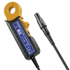
100 A AC, φ 15 mm (0.59 in), 2.5 m (8.20 ft) cord length
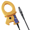
600 A AC, φ 46 mm (1.81 in), 2.5 m (8.20 ft) cord length
Leak current input (1)
*For leak current measurement (not capable of power measurement)
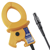
6 A AC, φ 40 mm (1.57 in), 2.5 m (8.20 ft) cord length
AC/DC current input (6)
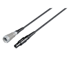
2 m (6.56 ft) length
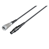
5 m (16.41 ft) length
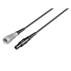
10 m (32.81 ft) length
Voltage input (8)
*The L1000 is bundled with PQ3198 *Please inquire about voltage cord extension

Red/ Yellow/ Blue/ Gray each 1, Black 4, 3m (9.84ft) length, Alligator clip ×8
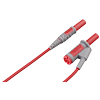
Banana branch-banana, Red: 1, 0.5 m (1.64 ft) length, for branching from the L9438s or L1000s, CAT IV 600 V, CAT III 1000 V
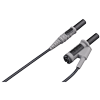
Banana branch-banana, Black: 1, 0.5 m (1.64 ft) length, for branching from the L9438s or L1000s, CAT IV 600 V, CAT III 1000 V

Attaches to the tip of the banana plug cable, Red/Black: 1 each, 185 mm (7.28 in.) length, CAT II 1000 V
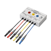
When three-phase 3-wire connection, the voltage cord to be connected can be reduced from 6 to 3
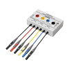
When three-phase 4-wire connection, the voltage cord to be connected can be reduced from 6 to 4

Attaches to the tip of cord, red ×1, φ11 mm (0.43 in)
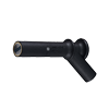
Attaches to the tip of cord, black ×1, φ11 mm (0.43 in)
Storage media (2)
*The Z4001 is bundled to PQ3198 only
SD Card Precaution
Use only the SD Card sold by HIOKI. Compatibility and performance are not guaranteed for SD cards made by other manufacturers. You may be unable to read from or save data to such cards.
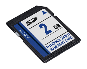
2 GB capacity
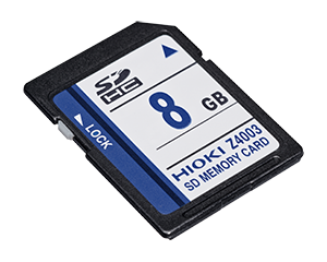
8 GB capacity
Power supply (2)
*The Z1002, Z1003 are bundled
For main unit, 100 to 240 V AC
NiMH, Charges while installed in the main unit
PC peripherals (1)
Time synchronization (1)
For PQ3198 only
To synchronize the PQ3198 / PW3198 clock to UTC
Other options (2)
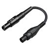
Used to connect the current sensors with BNC terminal to PL14 terminal (example the PQ3100)
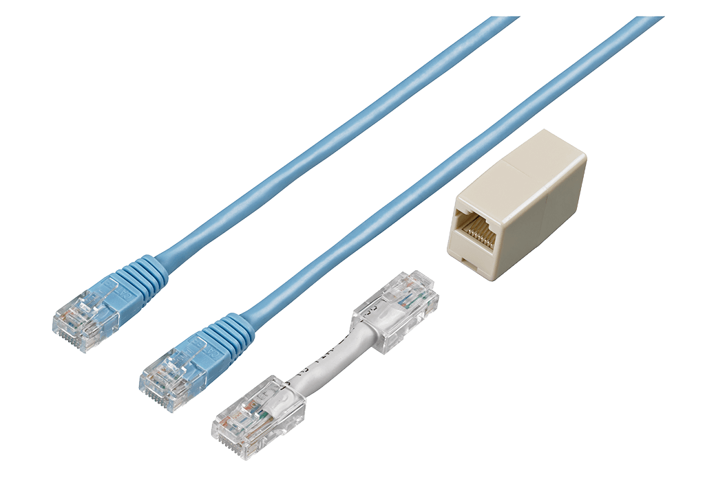
Straight Ethernet cable, supplied with straight-to-cross conversion adapter, 5 m (16.4 ft.)
Hands-free options (2)
When using with PQ3100 / PQ3198, suspend the main body on the metal surface using two Z5020 powerful type.
Z5004 hang the cords on the metal surface.

Extra strength
Cases (2)
Waterproof Box
For outdoor installation; IP65 compliant, Contact Hioki for a quotation.
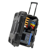
Hard trunk type, Includes compartment for options
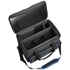
Bag type, Includes compartment for options
- Management of Measurement Data for UPS Sites to Facilitate the Digital Transformation
- On-site Inverter Measurement
- Verify the Power Quality and Efficiency of an EV fast charger
- TDD Measurement as Specified in the IEEE519 Standard
- Inspect the Stress on Factory UPS Caused by Voltage Dips
- Measure Periodical Instantaneous Voltage Drops
- Measure Transient Voltage Waveforms
- Test for Abnormal Waveforms when Switching to UPS Power
- Verify the Energy Savings Created By Photovoltaic (PV) Systems
- Measure the High-Order Harmonic Voltage and Current of Power Lines
- Power Quality Survey of Solar Power Generation Systems
- Measure the Noise Generated by Switching Power Factor Correction Capacitors
- Measure the Transient Voltage in Glowing Fluorescent Lights
- Measure Lightning-induced Voltage Dips in a Low-Voltage Circuit
- Measure Voltage Drop Caused by Wiring Impedance

