ISO 21782: EV Propulsion Component Test Specifications and Measuring Instruments
Proliferation of electric vehicles (EVs) is progressing rapidly in order to achieve carbon neutrality.
The ISO 21782 international standard was defined with the goal of facilitating impartial evaluation of EV performance testing methods.
This document provides an explanation so testing based on ISO 21782 can be carried out properly.
(This document was compiled by Hioki based on ISO 21782. It is not an official explanation of the standard)
Contents
1. Overview of ISO 21782
2. Standard structure and testing
3. Instruments necessary for testing
4. Recommended instruments
1. Overview of ISO 21782
Parts 1 through 3 and Part 6 of ISO 21782, “Electrically propelled road vehicles–Test specification for electric propulsion components,” were issued in August 2019. Parts 4, 5, and 7 were subsequently issued in May 2021.
ISO 21782 is an international standard, in contrast to various national standards on automotive motor systems including JIS D1302, UNR85, TRIAS-99-017-01, and GB/T 18488.1/2. It defines procedures for testing EV motor systems that take into account dynamic operations(acceleration and braking) that were not covered by previous standards, allowing performance and reliability to be comparatively evaluated in a fair manner.
(For more information about ISO 21782, please see ISO’s website. The standard’s detailed provisions can be purchased from the Japanese Standards Association[English only])
2. Standard structure and testing
IEC 7 defines the following test procedures:
-1. Part 1 ISO 21782-1:2019: General test conditions and definitions
-2. Part 2 ISO 21782-2:2019: Performance testing of the motor system
· Motor systems consisting of an inverter and motor, gross efficiency and gross loss across input and output power, temperature rise in system components, torque characteristics, and torque ripple testing
-3. Part 3 ISO 21782-3:2019: Performance testing of the motor and the inverter
· Loss and efficiency in the motor, inverter, and chopper; temperature rise; motor standalone torque characteristics; and cogging torque testing
-4. Part 4 ISO 21782-4:2021: Performance testing of the DC/DC converter
· Measurement of DC/DC converter loss and efficiency
-5. Part 5 ISO 21782-5:2021: Operating load testing of the motor system
· Repeated testing of a motor system operating as a combination of a pair inverter and motor at the limits of its specifications
-6. Part 6 ISO 21782-6:2019: Operating load testing of motor and inverter
· Durability operational testing of the motor and inverter; motor breaking strength verification testing
-7. Part 7 ISO 21782-7:2021: Operating load testing of the DC/DC converter
· Repeated operational testing using representative current output patterns for the DC/DC converter
Operating points
ISO 21782 defines the operating points used in testing, placing them at 2 s, 10 s, and 1800 s in each test.
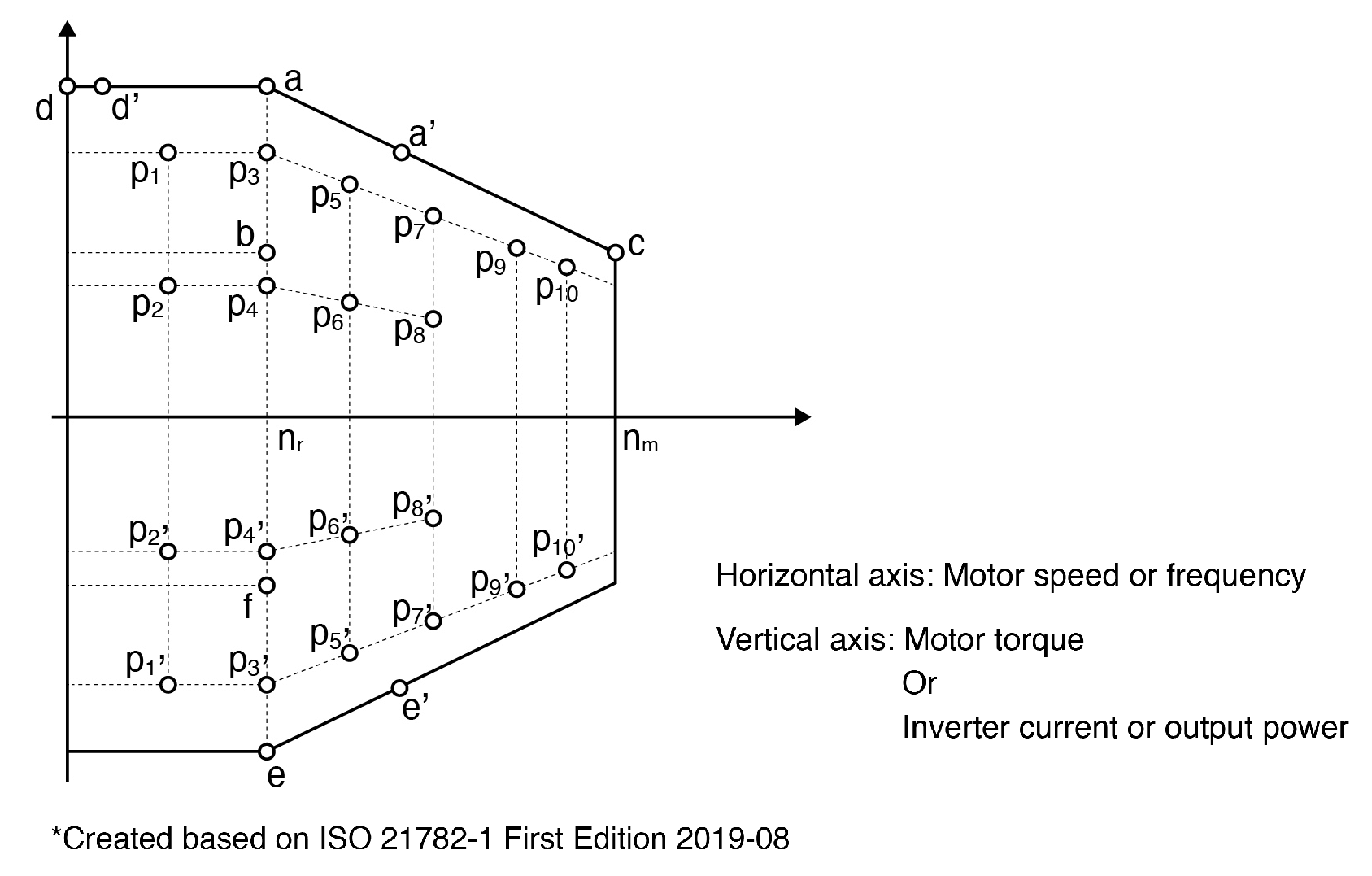
Measurement parameters
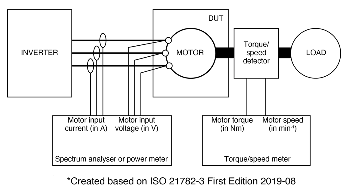
The standard provides a test diagram for each test in oder to measure the following parameters:
-1. Room temperature and humidity as defined by ISO 21782-1:2019 5.4 as ambient conditions
-2. Motor and inverter or chopper current and voltage
-3. Motor torque and speed
-4. Component temperatures
-5. Inverter output frequency
-6. Rotor speed
The standard recommends using the 3-power-meter method to measure 3-phase power.
Test reports
The appendices of Parts 2 through 7 provide examples of test reports.
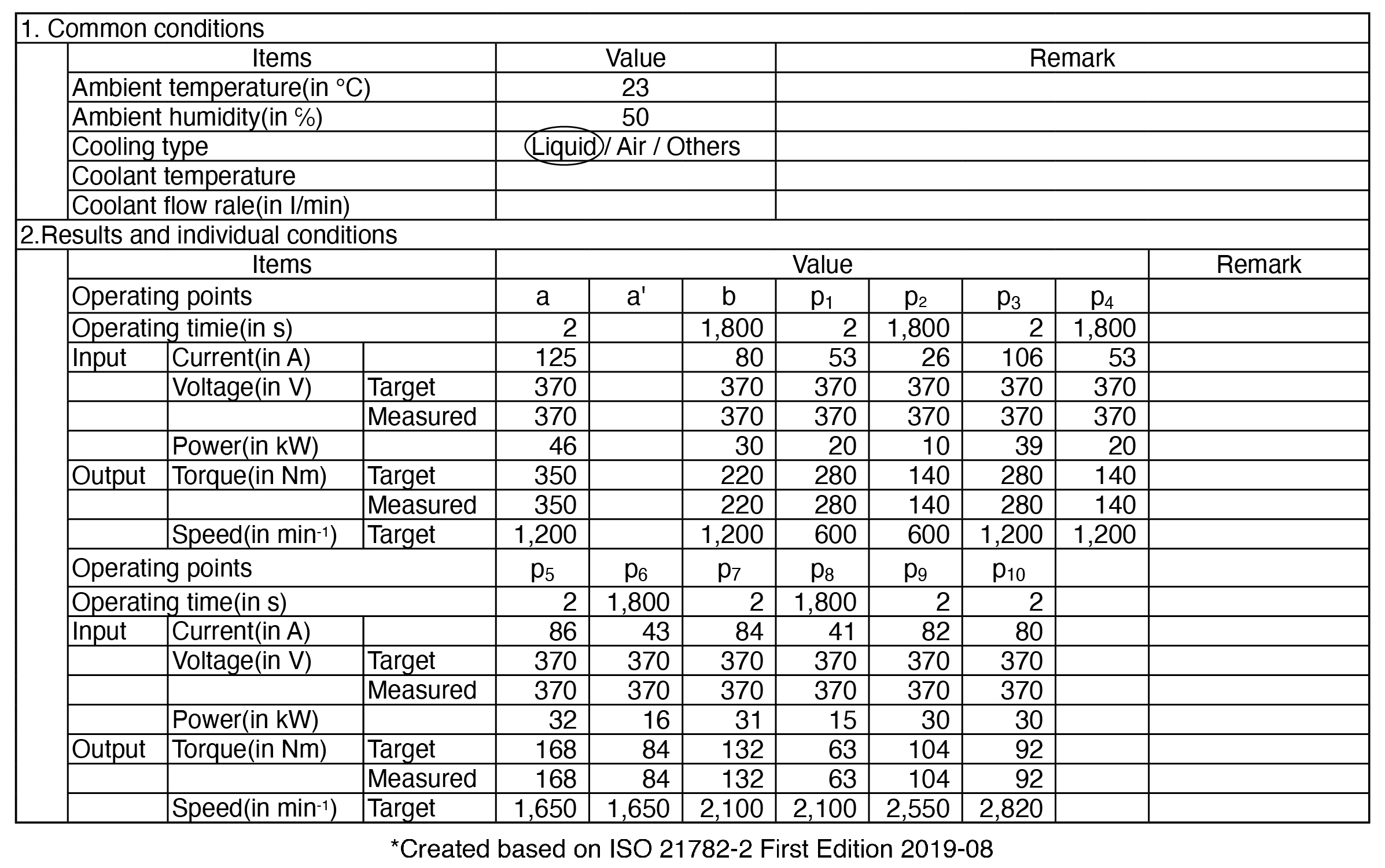
Measurement accuracy and recording intervals
Part 1 specifies the following:
-1. Current: ±1.0%, voltage: ±0.5%
-2. Torque: ±0.2%, motor speed: ±0.5%
-3. Temperature: ±2 K, relative humidity: ±5%
· All measured values other than temperature and relative humidity are measured and recorded at a sampling frequency of 10 Hz or greater
· Temperature and relative humidity are recorded at a sampling frequency of 1 Hz
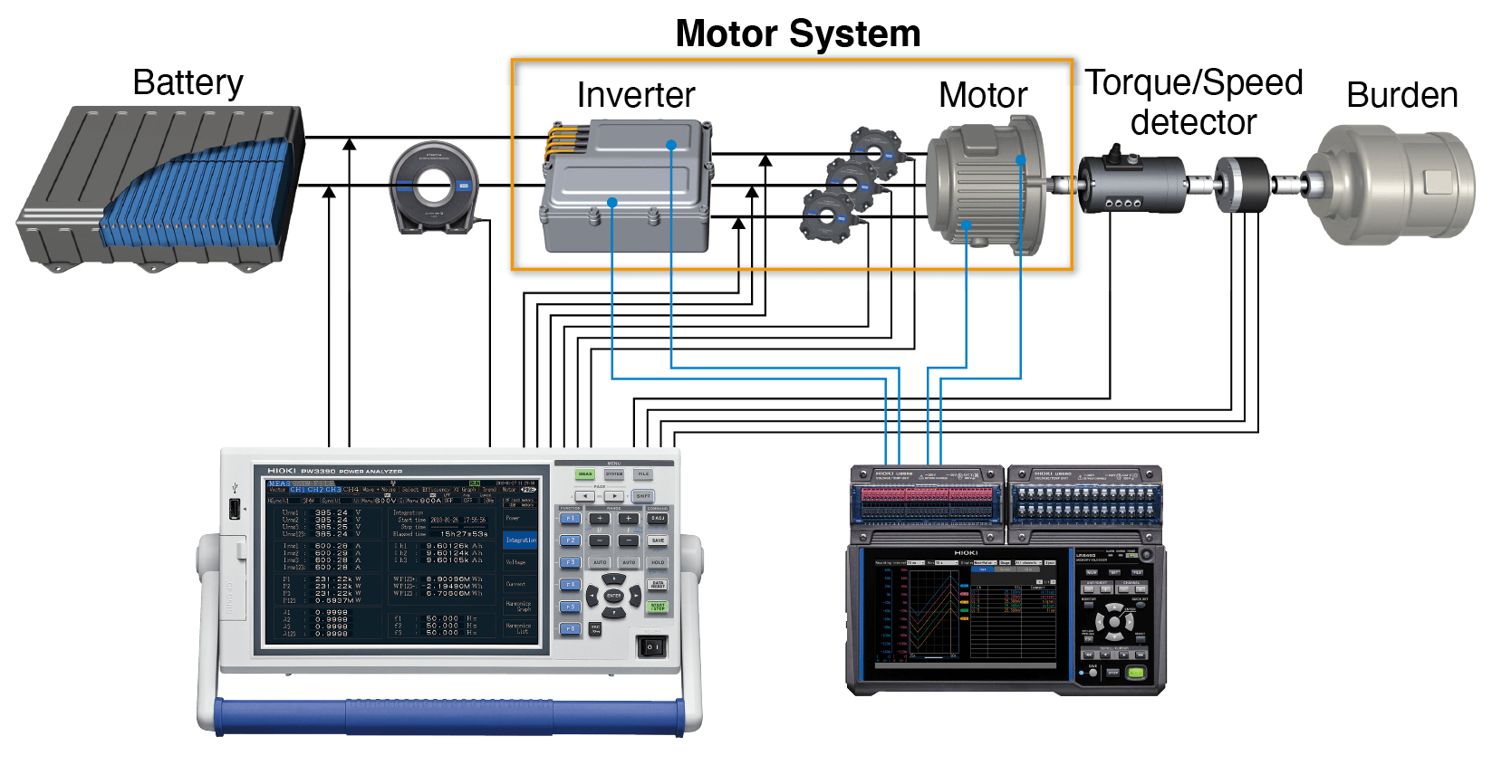
3. Instruments necessary for testing
· Voltage and current measurement: Power meter
· Motor torque and speed measurement: Torque/speed meter
→ Voltage, current, torque, and speed can all be measured with a Hioki power analyzer
· Temperature rise measurement: Thermometer or environmental temperature meter capable of measuring the necessary number of points
· Surge voltage measurement: Storage oscilloscope
→ Surge voltage waveforms can be acquired using a Hioki Memory HiCorder’s trigger function
· Motor system’s operating load measurement (verification that the electrical angle difference between the back electromotive force waveform and location sensor origin is less than 5°): Use a resolver sensor or an ABZ rotary encoder as an angle sensor to detect the angle of rotation
→ A Hioki Memory HiCorder can be used to measure the mechanical angle of the rotation’s origin based on the electrical signal from a resolver sensor or ABZ rotary encoder. A similar measurement can be made by combining a Hioki power analyzer with an ABZ rotary encoder
(The above test system requires other components, including a DC power source, load device, torque/speed detector, and dynamometer. A resolver sensor or ABZ rotary encoder is necessary as the rotation angle sensor)
Power measurement precautions
The operating points set forth by ISO 21782 cover a broad range, as shown below.
(50% of rated speed) to ([{Max speed – rated speed} x 90%] + rated speed)
The motor’s torque and the inverter’s current value and output power under those conditions range from 40% to 100% of their rated values. Inverter input consists of DC power. Consequently, the power meter used must demonstrate performance capable of measuring values ranging from DC to high-RPM values at a accuracy of ±1.0% for current and ±0.5% for voltage. In order to ensure the aforementioned accuracy for measuring large currents, the user must make sure that the accuracy (from DC to frequency corresponding to the respective high RPM) is the combined (i.e. sum) accuracy of both the current sensor and measuring instrument, not just of the measuring instrument.
Since the 3-power-meter method is recommended for use in 3-phase power measurement, the best instrument suited to the task is one that provides a total of at least four channels of input: one channel for DC input and three for 3-phase power.
4. Recommended instruments
Voltage, current, motor torque, and motor speed measurement
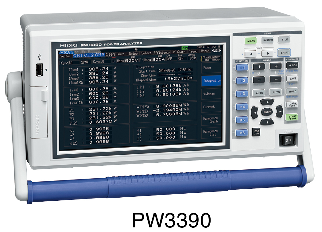
POWER ANALYSER PW3390
· Basic power accuracy: ±0.04% rdg. ±0.05 f.s.
· 200 kHz measurement band, and flat amplitude and phase accuracy up to and including high frequencies
· Simple power measurement using pull-through or clamp-on current sensors
· High-accuracy, high-speed calculation of transient-state power in 50 ms
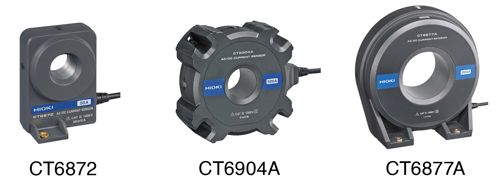
Current sensors (high-accuracy pass-through type)
CT6872
· Rated current: 50 A AC/DC; frequency band: DC to 10 MHz (-3 dB)
· Measurable conductor diameter: φ24 mm or less
CT6904A
· Rated current: 500 A AC/DC; frequency band: DC to 4 MHz (-3 dB)
· Measurable conductor diameter: φ32 mm or less
CT6877A
· Rated current: 2000 A AC/DC
· Frequency band: DC to 1 MHz (-3 dB)
· Measurable conductor diameter: φ80 mm or less
(For more information about Hioki’s line of current sensors, please see the HIGH ACCURACY / WIDEBAND CURRENT SENSOR Series brochure)
For higher-accuracy measurement
· POWER ANALYZER PW6001
· POWER ANALYZER PW8001
Multi-point temperature measurement
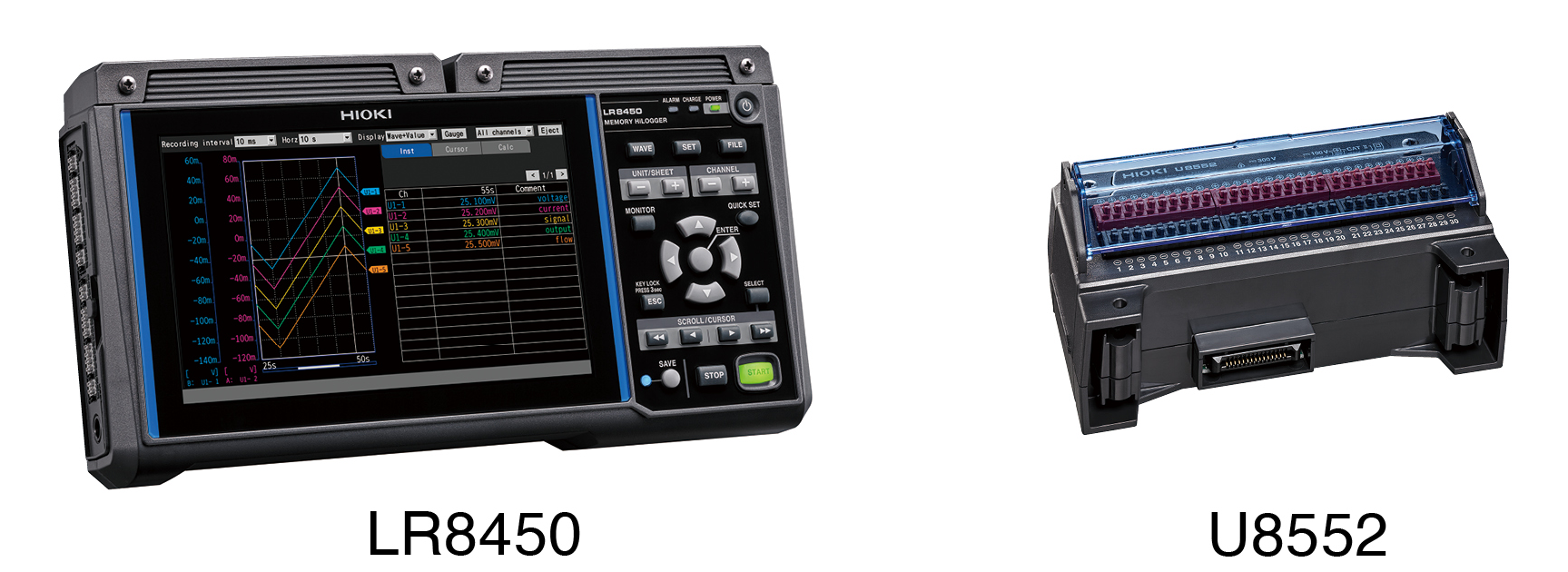
MEMORY HiLOGGER LR8450
MEMORY HiLOGGER LR8450-01 (wireless LAN model)
· LR8450: Can accommodate 4 temperature measurement modules such as the U8552
(total of 5 models available)
· 120-channel temperature measurement can be done with four U8552 modules
VOLTAGE/TEMP UNIT U8552
· Number of channels: 30 (scan method)
· Maximum sampling speed (data refresh):
10 ms (15 or less channels in use)
20 ms (16 to 30 channels in use)
· Measurement targets: Voltage, temperature (thermocouple), humidity (using the Z2000 Humidity Sensor)
· Input terminals: Push-button terminal block
For faster measurement
· MEMORY HiCORDER MR8740-50
Rotation angle origin measurement
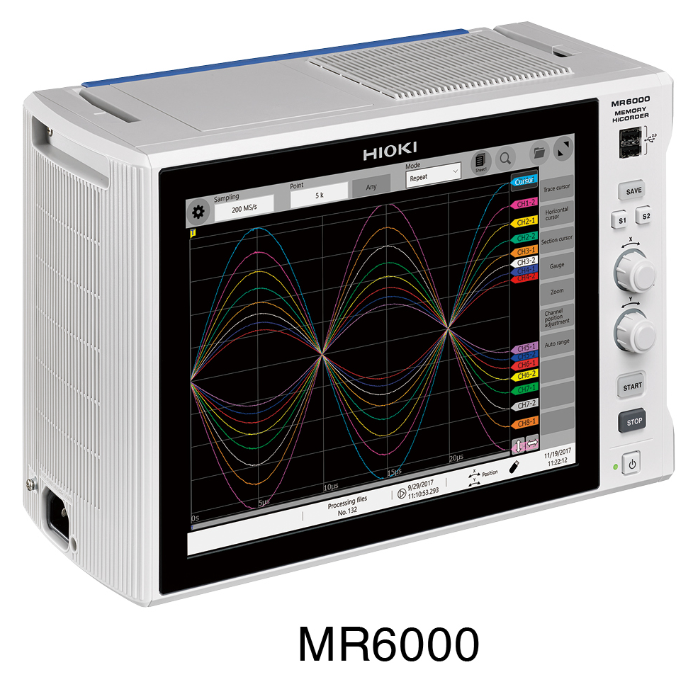
MEMORY HiCORDER MR6000
· High-speed insulation measurement at 200 MS/s, wide band from DC to 30 MHz
(used with U8976 High-Speed Analog Unit)
· The required measurement input modules may vary depending on the setup.
(please contact your closest Hioki dealer for details)
· Long memory capacity (1 gigaword)
· Angle rotation measurement using waveform processing
(supports for resolver sensors and ABZ rotary encoders)
Rotation angle measurement
· Resolver sensor
· Rotary encoder
(For more information about Hioki’s line of input units/modules, please see the MOMORY HiCORDER MR6000 brochure)