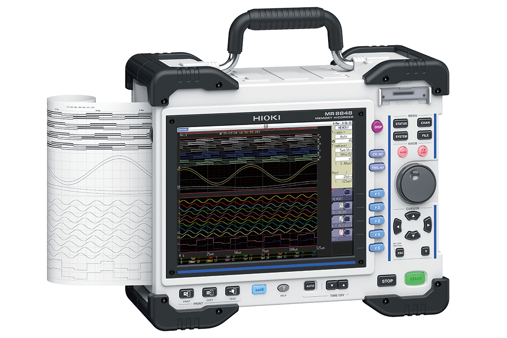
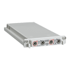
MEMORY HiCORDER MR8848
Engineered for Extremes, Trusted for Precision
-
 Internal Storage U8334: 1 year
 -

-

-

-

-

Infrastructure such as electric power facilities, data center UPSs, and railroads must operate with stability and zero downtime. High-precision waveform recording with the Memory HiCorder is essential to ensure safe and reliable operation of critical infrastructure.
Sturdy High-Speed DAQ System
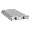
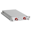
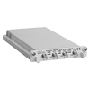
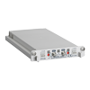
The Memory HiCorder MR8848 is a recording device used in fields such as power plants, railways, and industrial plants to measure transient phenomena.
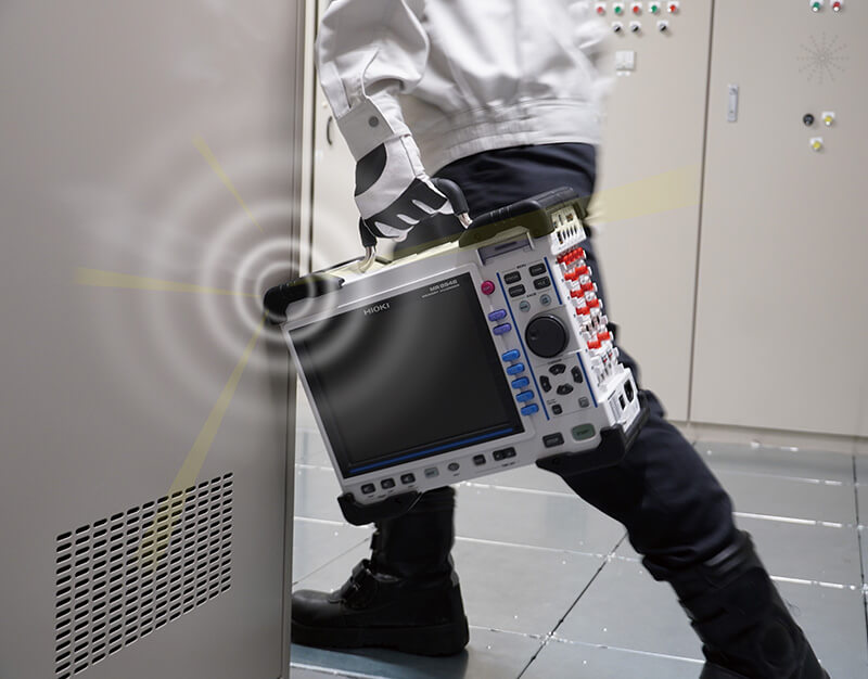
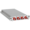
The robust housing design has passed rigorous tests such as drop tests and vibration tests.
With high-speed sampling that captures the voltage and current waveforms of inverters, large-capacity memory that stores entire events, and multi-channel measurements that allow for the verification of correlations between multiple signals, it ensures that you won't miss critical waveforms.
Key Features
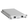
- Work anywhere with a durable, shock-resistant, portable design
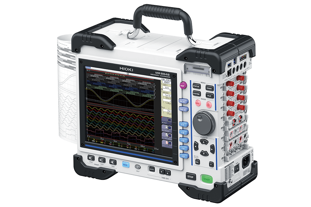
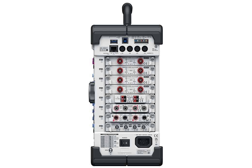
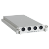
- Safely measure with isolated channels
- Handle complex tasks using 32 analog & 64 logic channels
- Record for extended periods with high-capacity memory
- Make pass/fail judgments with waveform & numerical analysis
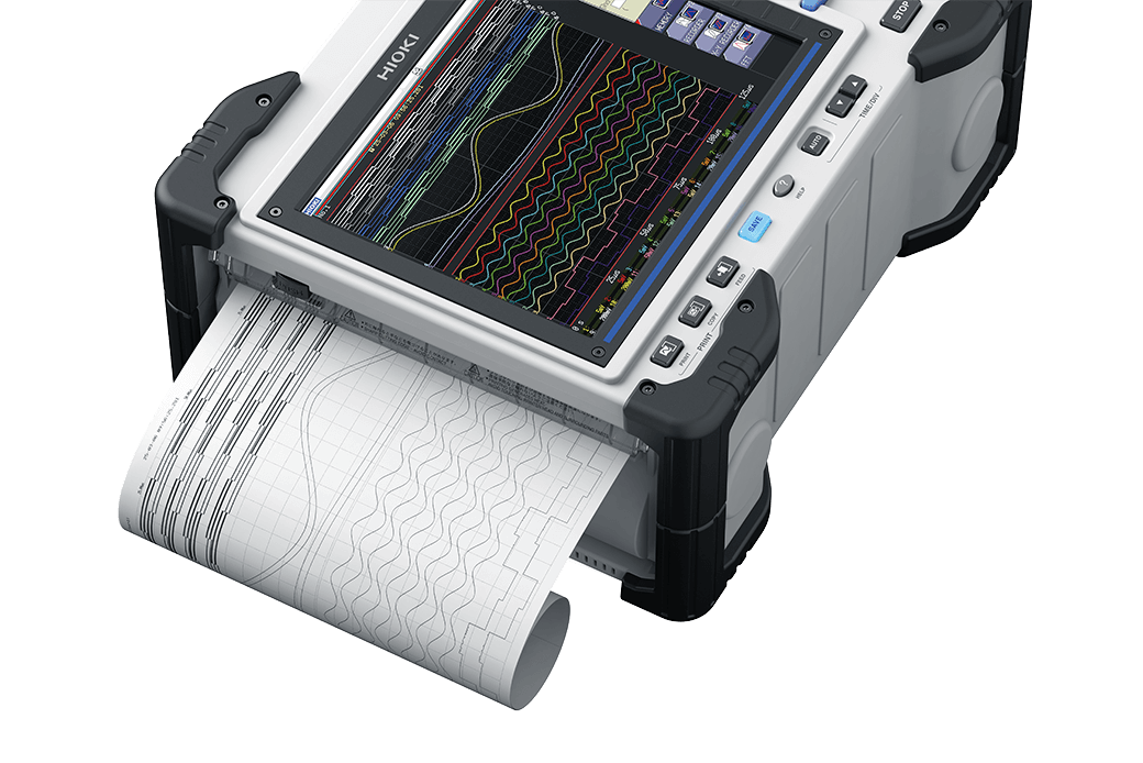
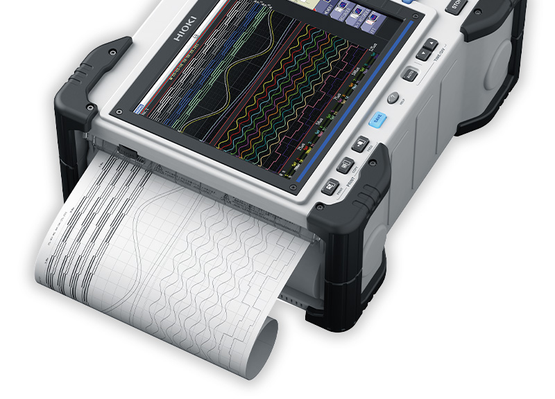
- Check printed waveforms on-site using a built-in printer (optional)
Model No. (Order Code)
| MR8848 |
|---|

For Evaluation Testing and Troubleshooting
Robust Housing
To minimize the risk of failure due to drops and shocks, the Memory HiCorder MR8848 employs a rugged housing with protectors for enhanced durability.
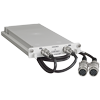
Safe and Reliable Measurements
When inspecting lines of differing electrical systems simultaneously (e.g., power lines and signals), short-circuit are a serious risk. Unlike oscilloscopes, memory HiCorders have isolated channels, so short-circuit accidents will not occur between differing circuits.

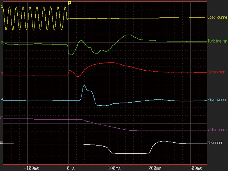
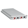
Correlation Analysis of Various Physical Phenomena
Troubleshooting and analysis can be more in depth than ever before through simultaneous recording of various physical phenomena.
The Memory HiCorder MR8848 records and analyzes multiple physical parameters—including voltage, current, temperature, vibration, pressure, and strain—for identifying correlations and root causes.
Onsite, Tamper-Proof Printing (Factory-Installed Option)
The factory-option printer lets you immediately print and share tamper-proof hard copies of your measurements right at the site, so that data cannot be tempered with.
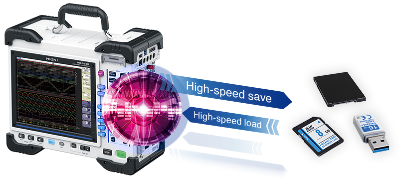
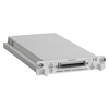
Record Long-Duration Waveforms with High-Capacity Storage
Long-term waveform recording becomes possible by storing data on the large-capacity 1 TB SSD (U8334) with the Direct Write to Storage option (MR9001-01).
For example, in railway vehicle measurement, the Memory HiCorder will record over 10 parameters at a sampling rate of 10 µs/S for more than an hour.
Basic specifications
| Measurement functions | Memory function (waveform recording), Recorder function (peak/trough recording), X-Y Recorder function, FFT function |
|---|---|
| Max. number of channels | 16 ch analog + 16 ch logic 32 ch analog + 16 ch logic (when U8975 or U8978 × 8 is attached) 10 ch analog + 64 ch logic (when main unit logic + Logic Unit 8973 × 3 is attached) 20 ch analog + 64 ch logic (when U8975 or U8978 × 5 + main unit logic + Logic Unit 8973 × 3 is attached) |
| Module slots | Up to 8 modules Restrictions: Current Unit 8971: up to 4 modules can be installed. Logic Unit 8973: up to 3 modules can be installed. 3CH Current Unit U8977: up to 3 modules can be installed. |
| Number of main unit logic channels | 16 (The GND of the logic probe input connector is common with the main unit GND) When the Digital Voltmeter Unit MR8990 is installed in Unit 1 and 2, the main unit logic cannot be used. Following restrictions when using the main unit logic (when logic measurement is turned ON): - The measurement resolution of the modules installed in Unit 1 and 2 will be limited to 12 bits. - Frequency modules installed in Unit 1 and 2 cannot be used. |
| Max. sampling speed | 20 MS/s for simultaneous use of all channels (when using the Analog Unit 8966) 10 MS/s for external sampling |
| Memory capacity | Total 512 megawords (no memory expansion) (16 megawords/ch using 32 analog channels, 256 megawords/ch using 2 analog channels) |
| Power supply | 100 V to 240 V AC, 50/60 Hz, 10 V to 28 V DC (when using the DC Power Unit 9784) |
| Max. rated power | 130 VA (220 VA when using the Printer Unit U8351) |
| External interfaces | LAN, USB, external control terminals |
| External storage | SD card slot, built-in drive (1 TB, factory-installed option), USB flash drive |
| Printer | When the factory-installed option Printer Unit U8351 is installed. Thermal recording method, use the Recording Paper 9231, recording speed 50 mm/s |
| Other functions | Trigger, numerical calculation, waveform calculation, storage partitioning, cursor measurement, monitor, position display (VIEW), waveform evaluation, waveform generation |
| Dimensions and weight | Approx. 351W × 261H × 140D mm (13.8W × 10.3H × 5.5D in.) (excluding protrusions) Approx. 365W × 307H × 160D mm (14.4W × 12.1H × 6.3D in.) (including protrusions) Approx. 6.9 kg (15.2 lbs.) (main unit only) Approx. 7.4 kg (16.3 lbs.) (when the Printer Unit U8351 is installed) |
| Included accessories | Startup Guide × 1, Operating Precautions × 1, input cord label × 1, power cord × 1, Recording Paper (when Printer Unit U8351 is installed) × 1, roll paper attachment (when Printer Unit U8351 is installed) × 2 |
Factory-installed option (3)
Please specify these requirements when placing your order, as it will be built in during production.
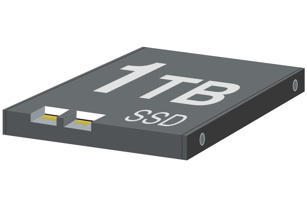
1 TB, FAT32, 1 year product warranty
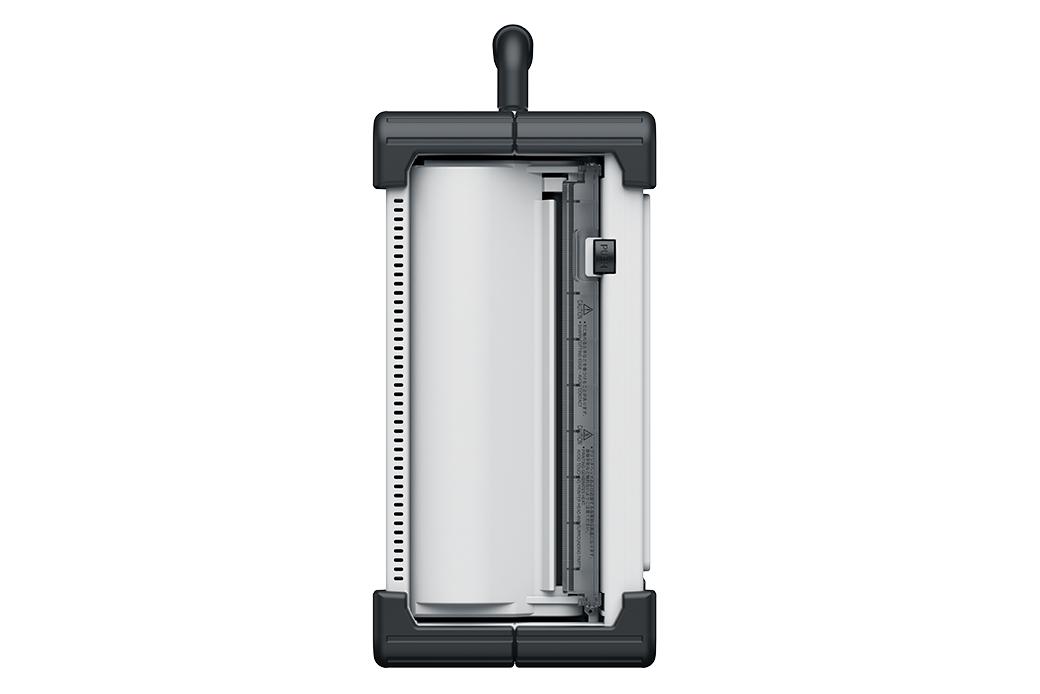
Thermal recording method, 50 mm/s max. recording speed
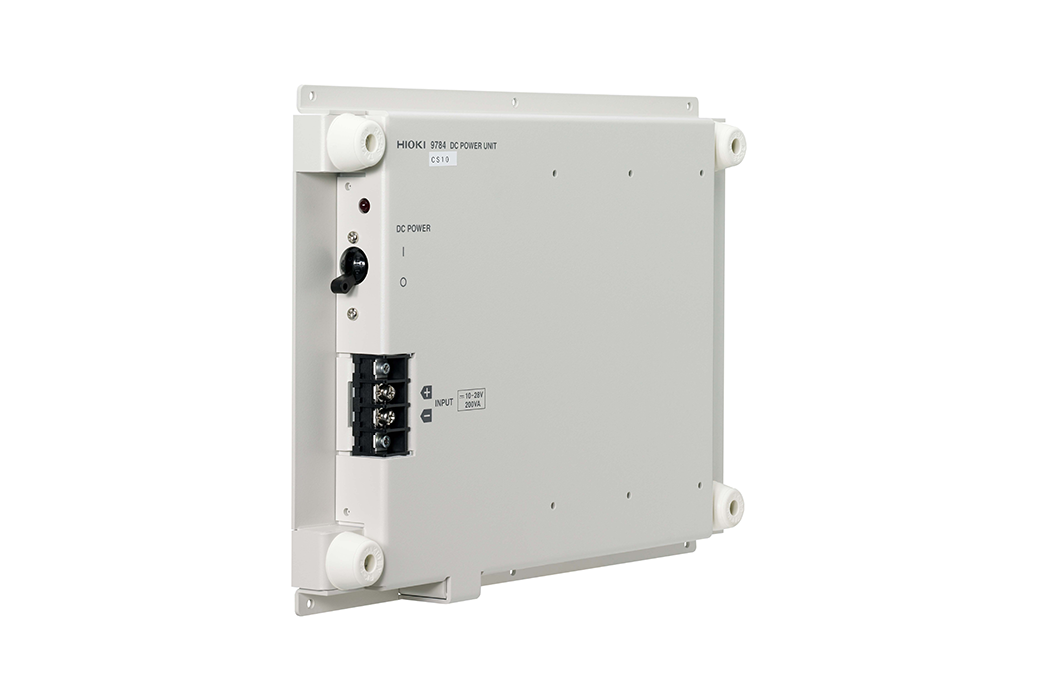
Factory-installed option (not user-installable, built in on the bottom casing, 10 to 28 V DC)
Additional function (1)

Function to record measurement waveforms directly to storage devices (one-time purchase of license key)
Input modules (14)
Input cables are not included; please purchase them separately. Up to three U8977 3CH CURRENT UNIT modules can be installed in a single MR8848.


Output modules (3)
Output cables not included. Please purchase them separately.
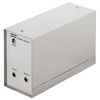
Carrying case (1)
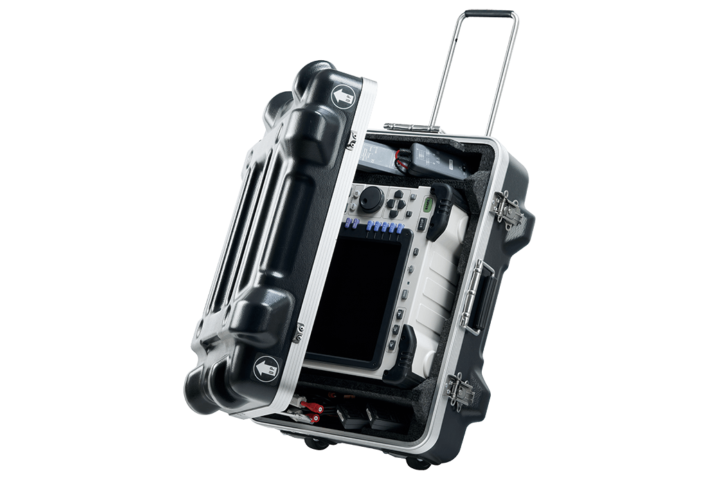
Equipped with an options compartment, durable hard-type trunk
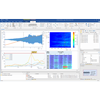
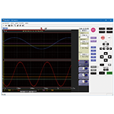
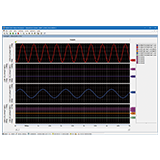
PC Software (4)
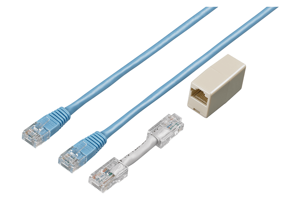
Straight Ethernet cable, supplied with straight-to-cross conversion adapter, 5 m (16.4 ft.)
Storage media (3)
Please be sure to use Hioki's optional storage media. If you use storage media made by other manufacturers, saving or reading data may not function properly, and we cannot guarantee the compatibility and performance.
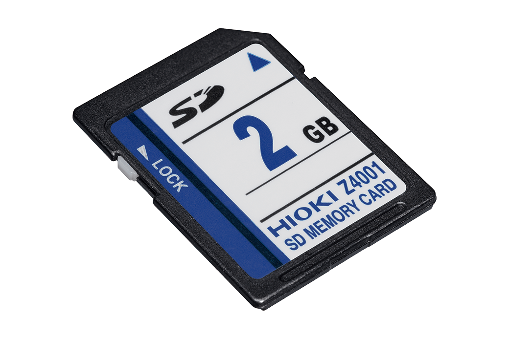
2 GB capacity
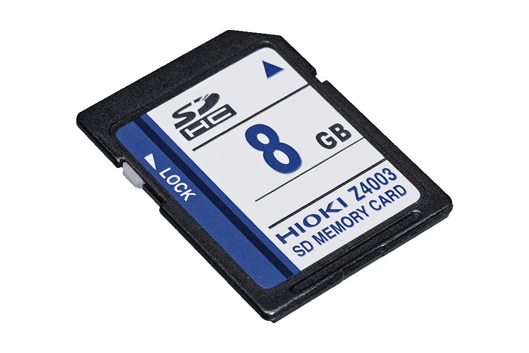
8 GB capacity
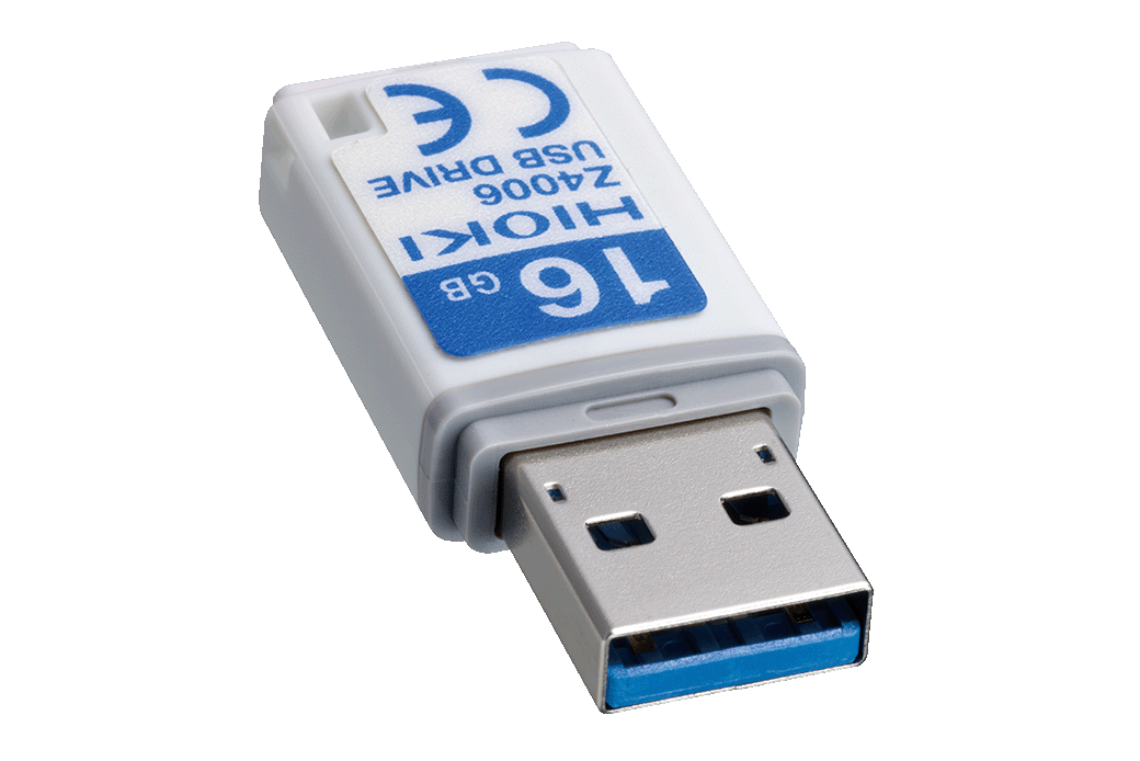
16 GB, long-life, high-reliability SLC flash memory
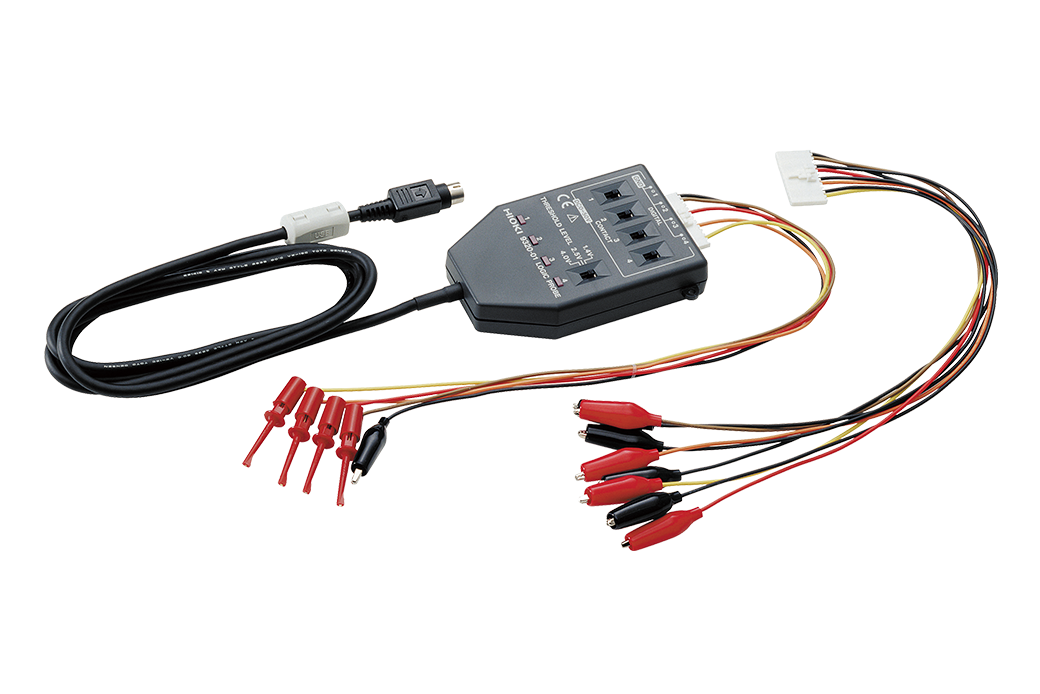
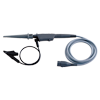
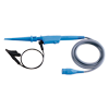
Logic probe (3)
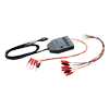
Recording paper (1)
For Printer Unit U8351
Roll type A4 width 216 mm (8.50 in) × 30 m (98.43 ft), 6 rolls/set
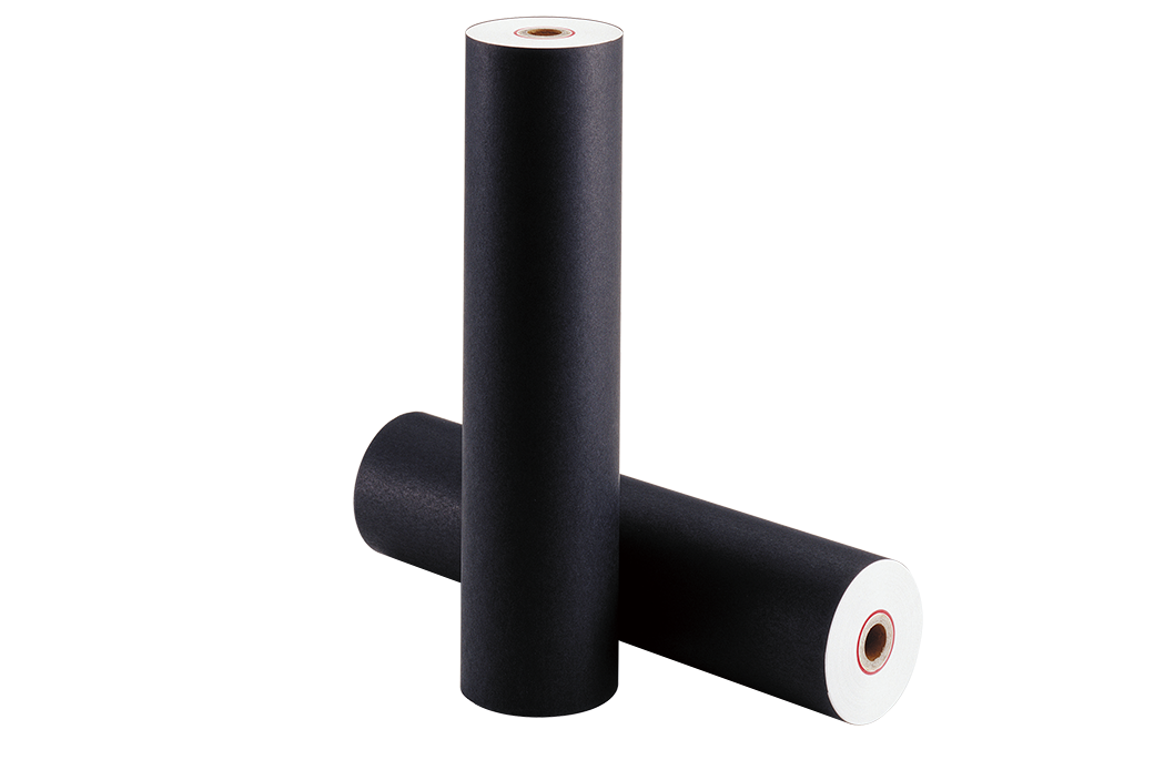
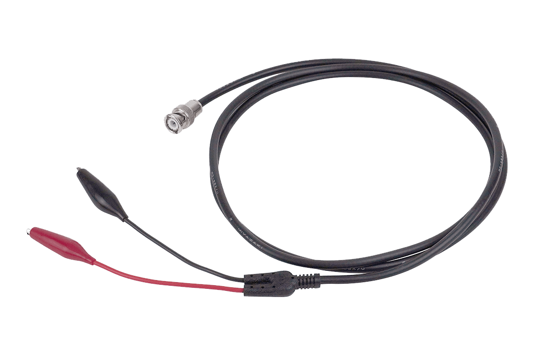
Output cable (2)
Max. rated voltage to earth: 33 V rms AC or 70 V DC, SMB to alligator clip, 1.5 m (4.92 ft.) length
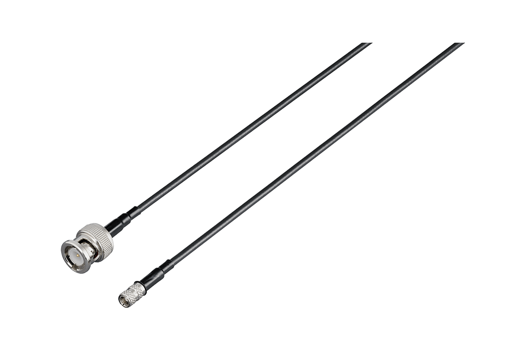
Max. rated voltage to earth: 33 V rms AC or 70 V DC, SMB to BNC terminal, 1.5 m (4.92 ft.) length
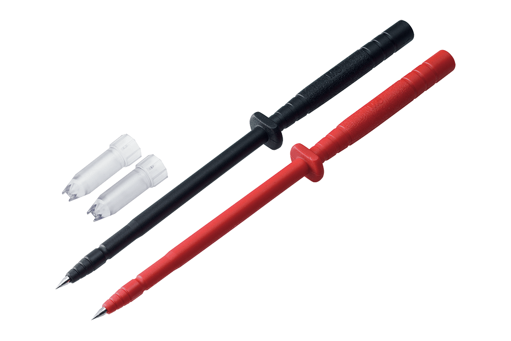
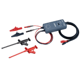
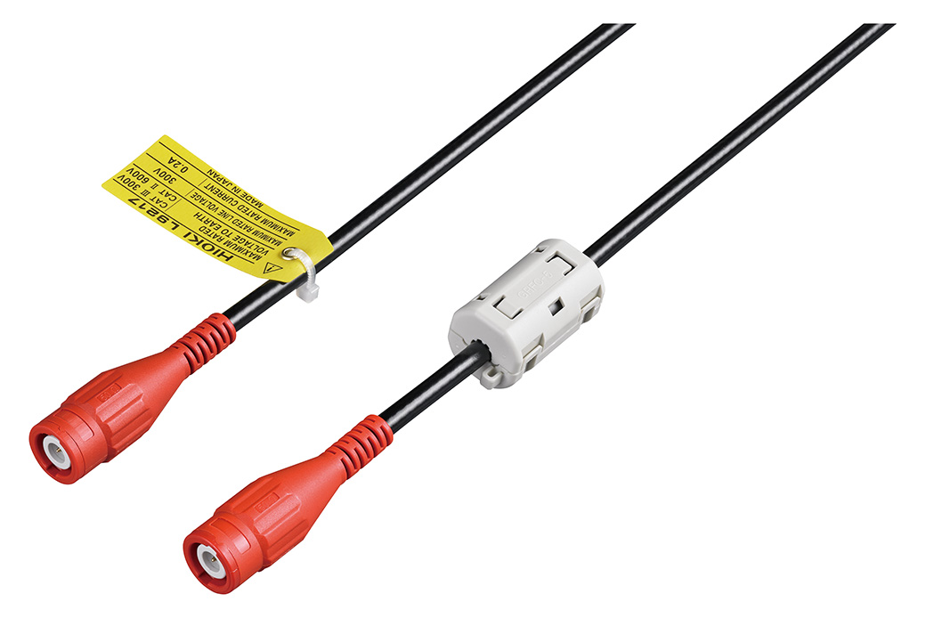
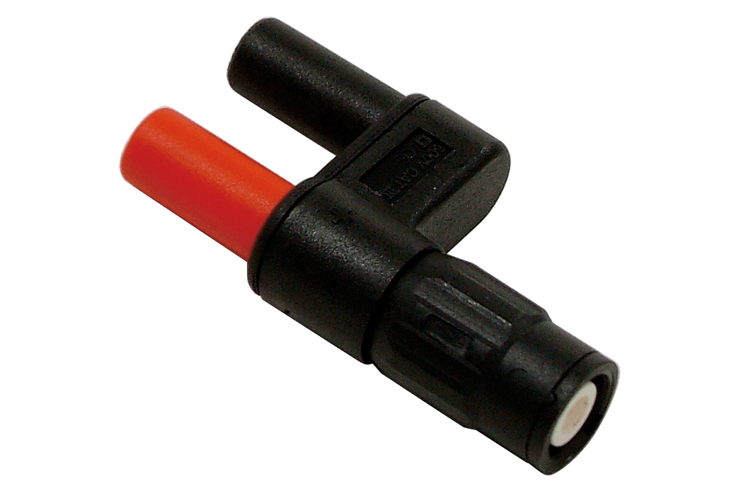
Input cable A (4)
Input voltage is limited to the specifications of the input modules in use.
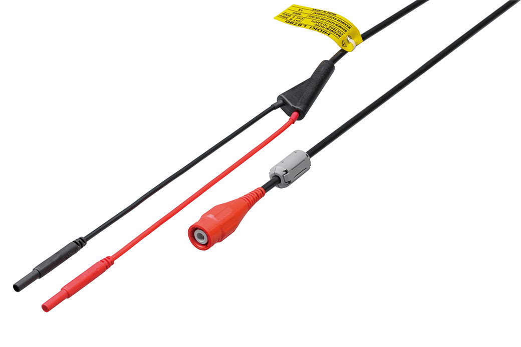
• Flexible φ 4.1 mm (0.16 in) thin dia.
• Cable allowing for up to 600 V input
• 1.8 m (5.91 ft) length
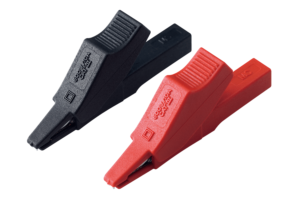
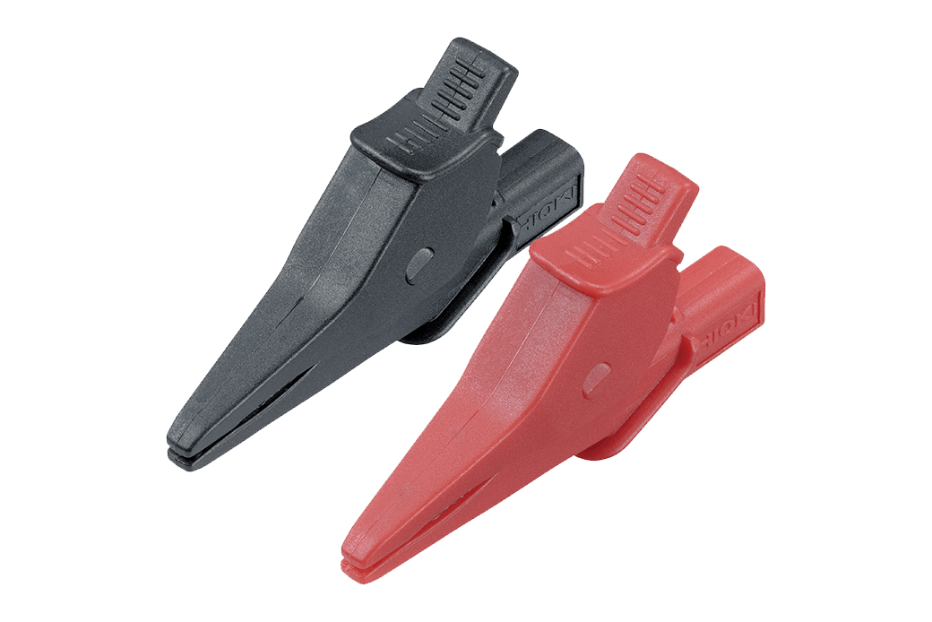
Red/black set attaches to the ends of the Connection Cord L9790
Red/black set attaches to the ends of the Connection Cord L9790
Red/black set attaches to the ends of the Connection Cord L9790
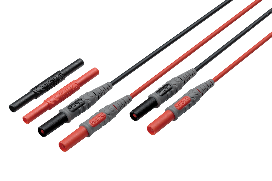
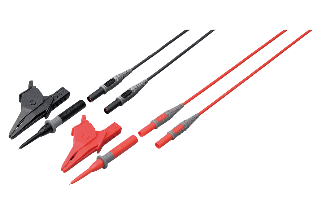
Input cable B (3)
Input voltage is limited to the specifications of the input modules in use.
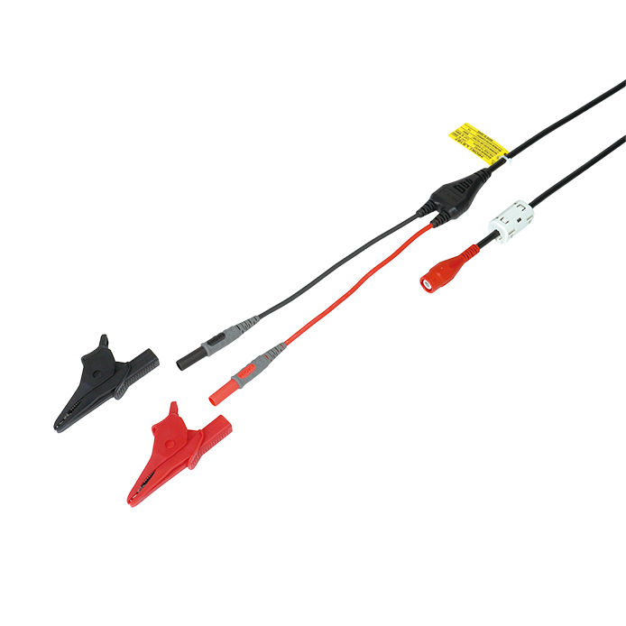
•φ 5.0 mm (0.20 in) dia
•Cable allows for up to 600 V input
•1.8 m (5.91 ft) length
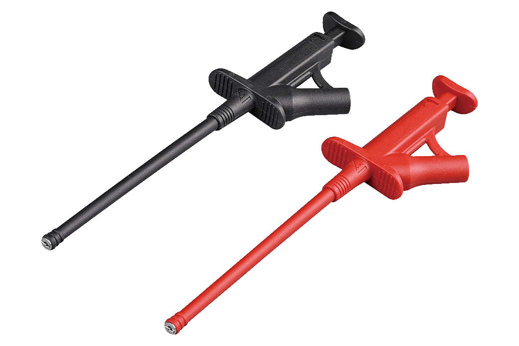
•Includes detachable large alligator clips
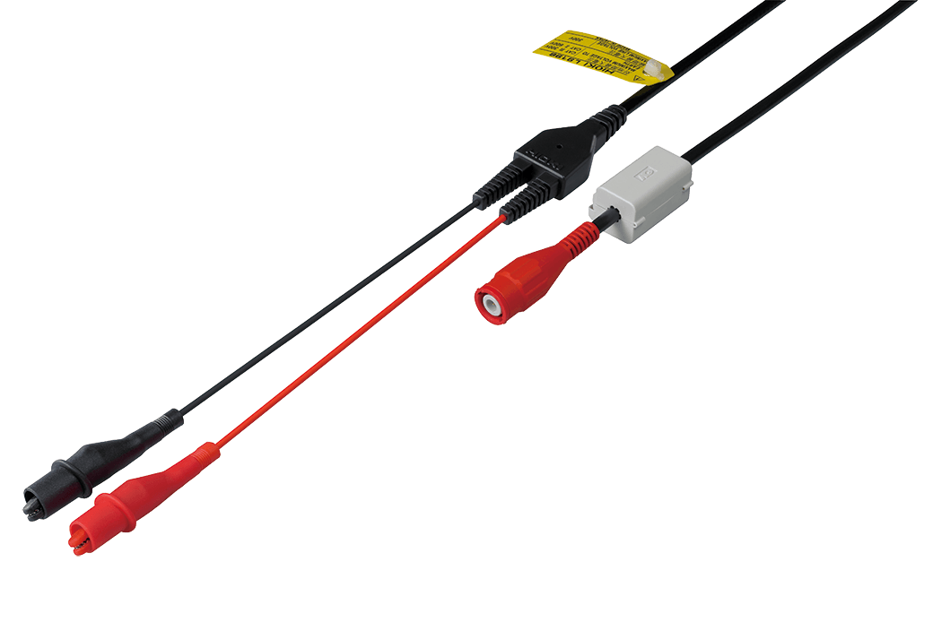
•φ 5.0 mm (0.20 in) dia.
•Cable allows for up to 300 V input
•1.7 m (5.58 ft) length
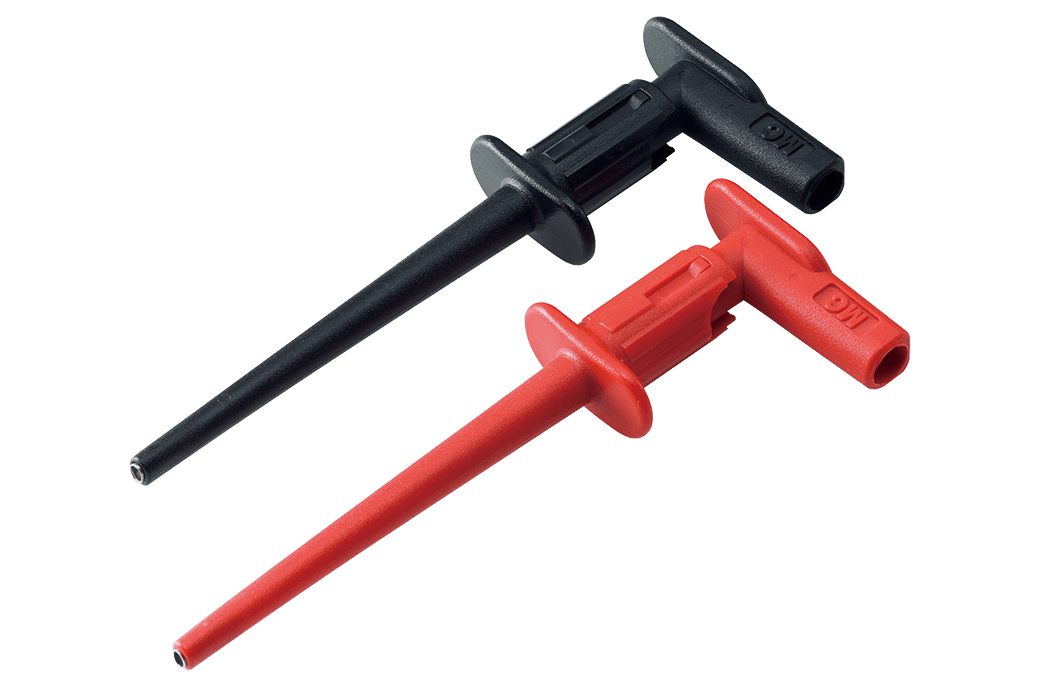
•Small alligator clip
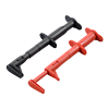
Attaches to the tip of the banana plug cable, Red/Black: 1 each, 185 mm (7.28 in.) length, CAT II 1000 V
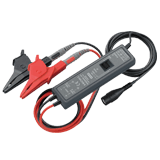
Input cable C (2)
The maximum input voltage is derated depending on the input frequency. For details, please refer to the instruction manual of each probe.
Input cable D (2)
The voltage to ground must be within the specified specification of the product. Power supply is required separately.
Input cable E (2)
The voltage to ground must be within the specified specification of the product. Power supply is required separately.
100 to 240V AC
Input cable F (8)
For banana terminals.
Input voltage is limited to the specifications of the input modules in use.
Z5058 and Z5059 are bundled with the L4931.
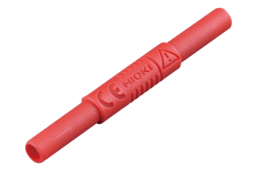
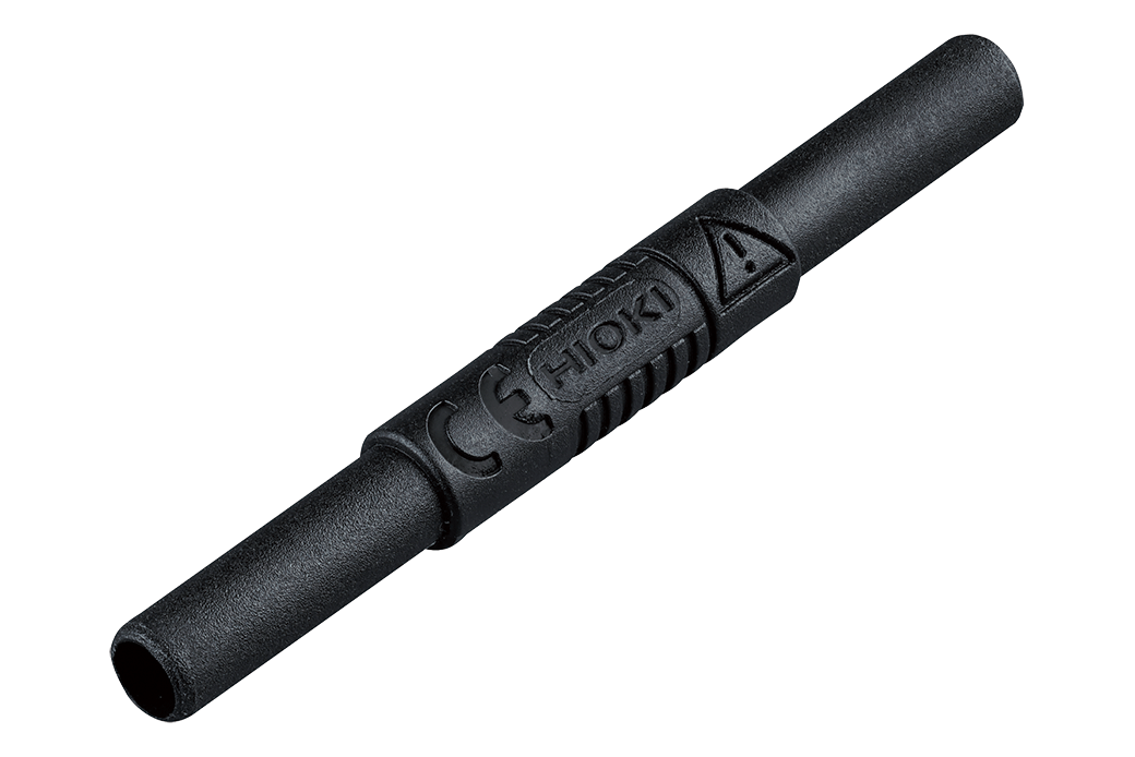
Expands the length of L4930/4940, 1.5 m (4.92 ft) length
Attaches to the tip of the L4930/4940, CAT IV 600 V, CAT III 1000 V
Attaches to the tip of the L4930/4940, CAT III 600 V
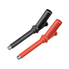
Attaches to the tip of the L4930/4940, CAT III 1000 V
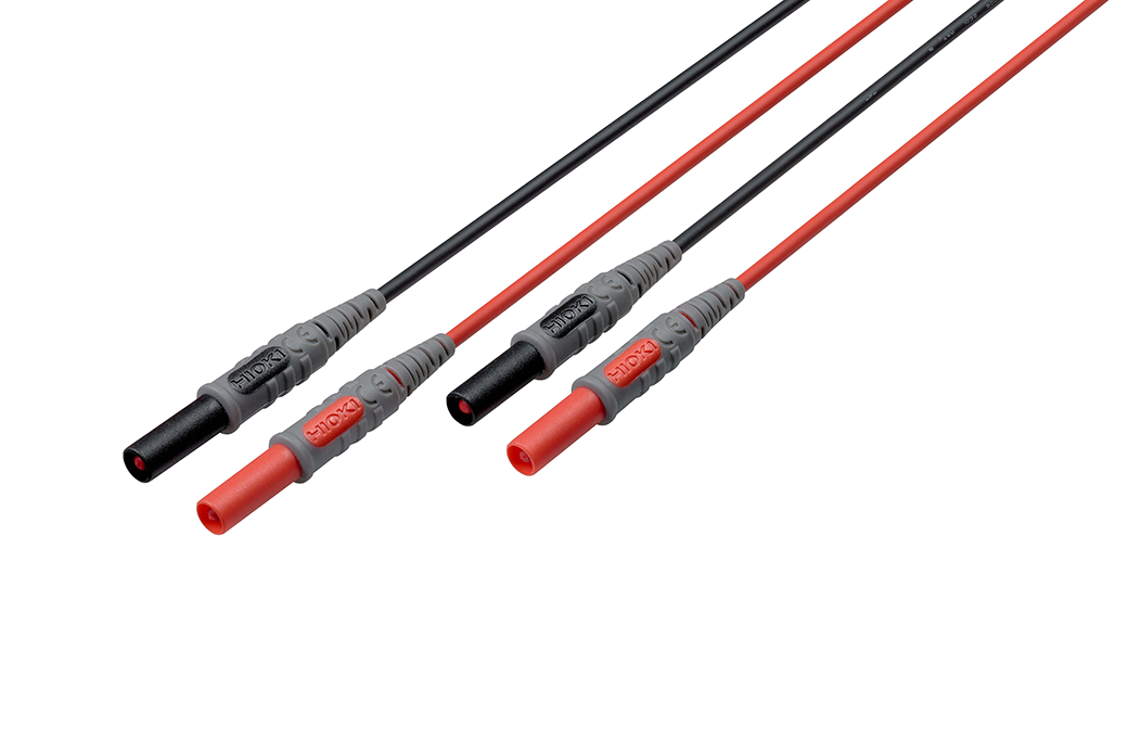
Banana plug - banana plug, 1.5 m (4.92 ft) length, red/black each 1
Attaches to the tip of the banana plug cable, Red/Black: 1 each, 185 mm (7.28 in.) length, CAT II 1000 V
For L4931
For L4931
Input cable G (1)
For MR8990. Input voltage is limited to the specifications of the input modules in use.
70 cm (2.30 ft.) length, detachable large alligator clips or needle tips are bundled, CAT IV 600 V, CAT III 1000 V
Input cable H (1)
For U8979.
Metal BNC to clip, 1.5 m (4.92 ft.) length
Other options for input (2)
Cord has insulated BNC connectors at both ends, 1.6 m (5.25 ft) length
Receiving side banana (female), output BNC (male)
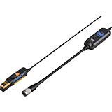
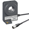
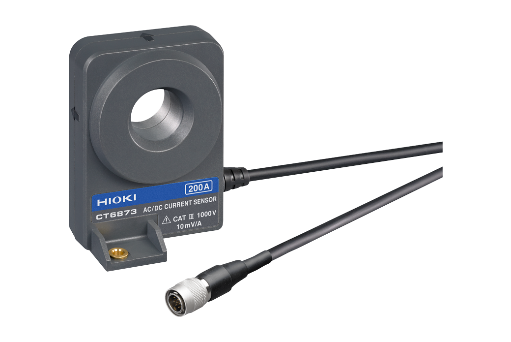
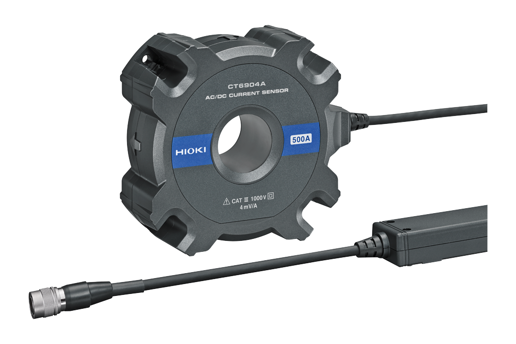
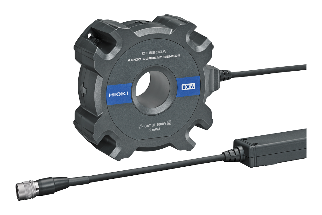
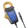
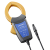
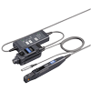
Current measurement (high-accuracy) (20)
ME15W (12pin) terminal type
Power supply is required separately to use the current sensors. The CT6847A current sensor can be connected to up to two units per U8977 3CH CURRENT UNIT, and up to a total of five units per MR8848.
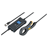

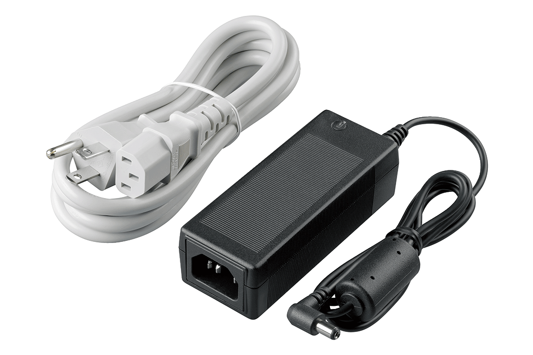
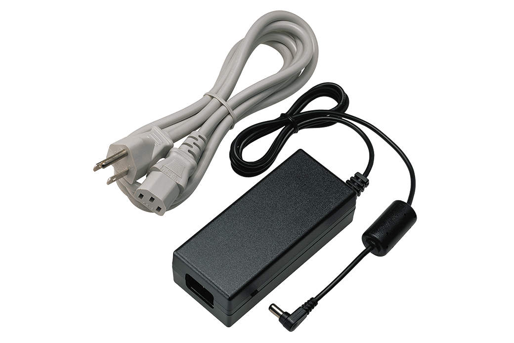
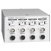
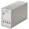
Power supply (for high-accuracy current) (4)

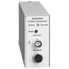
Cord has insulated BNC connectors at both ends, 1.6 m (5.25 ft) length
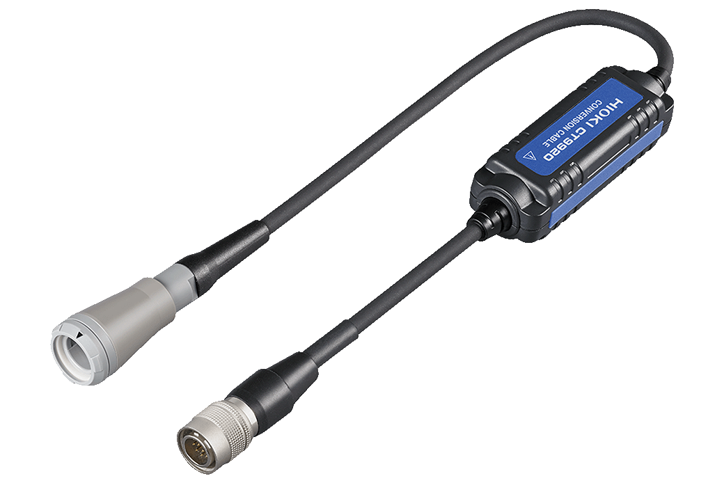
Conversion cable (1)
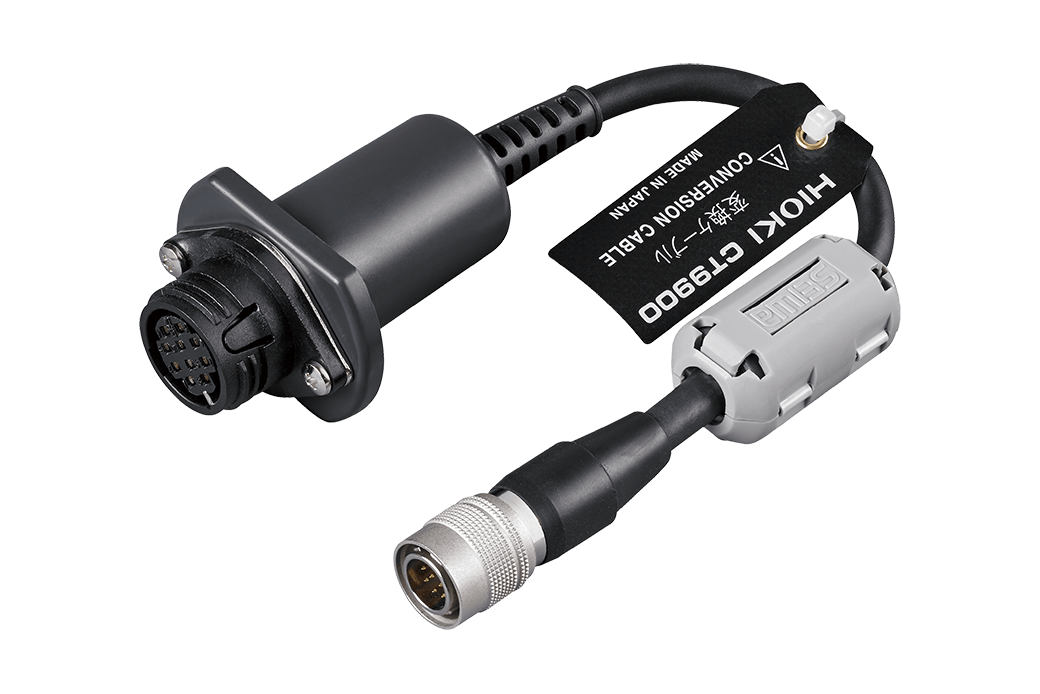
Convert PL23 (10-pin) terminal to ME15W (12-pin) terminal
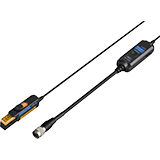
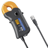
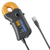
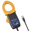
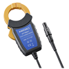
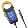
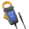
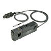
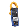
Current measurement (general use) (8)
PL14 terminal type
Conversion Cable CT9920 is required separately to use the current sensors.
Required to connect the PW4001 or other instrument’s ME15W terminal to a current sensor with a PL14 output connector.
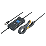
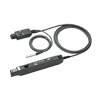
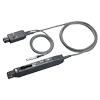
Current measurement (high-sensitivity, wide-bandwidth) (8)
Power supply is required separately to use the current probes.

Power supply (for high-sensitivity, wide-bandwidth current) (2)
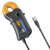
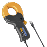
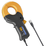
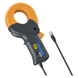
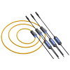
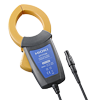
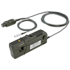
Leak current (2)
100 V to 240 V AC
-
MEMORY HiCORDER MR8848
 Test Report
Japanese
Test Report
Japanese
English Ver.01 -
MEMORY HiCORDER MR8848
Instruction Manual
Korean
Ver.00
-
MEMORY HiCORDER MR8848
Instruction Manual
English
Ver.00
-
MEMORY HiCORDER MR8848
Instruction Manual
Simplified Chinese
Ver.00
-
MEMORY HiCORDER MR8848
Startup Guide
Korean
Ver.00
-
MEMORY HiCORDER MR8848
Startup Guide
Simplified Chinese
Ver.00
-
MEMORY HiCORDER MR8848
Startup Guide
English
Ver.00
-
MEMORY HiCORDER MR8848
Ver.00
-
MEMORY HiCORDER MR8848
Ver.00
- Automatically detect abnormalities during durability testing
- Ensuring Uninterrupted Power: Effective Strategies for UPS Operation Testing
- Ensuring Safe Load Rejection Testing in Hydroelectric Power Plants
- Trip Testing of High-voltage Circuit Breakers in Power Transformer Installations
- Using Current Measurement to Diagnose Arc Welding Quality and Ensure Traceability