Testing for Protection Against Electrocution in Electric and Hybrid Vehicles
Vehicle Safety During Operation and After a Collision

NHTSA Federal Motor Vehicle Safety Standard (FMVSS) No. 305
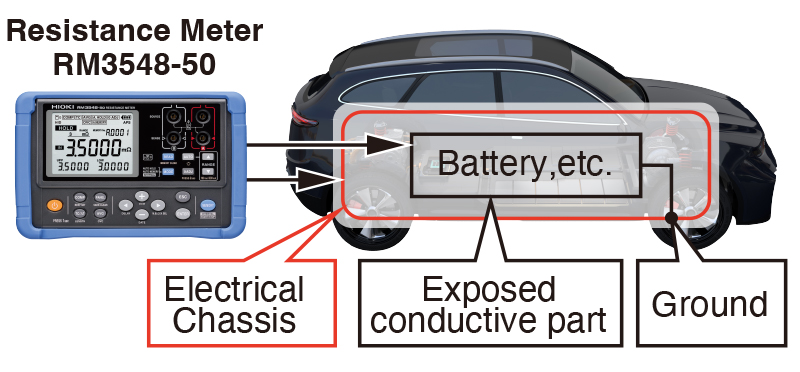
• The resistance between all exposed conductive parts of electrical protection barriers and the electrical chassis shall be less than 0.1 Ω; and
Test Methods and Equipment
Safety authorities do not specify a particular model or brand of instrument to verify resistance values but do stipulate test methods to be carried out by either a resistance meter or combination of DC power supply, voltmeter and ammeter. When using a resistance meter, one that can measure current levels of at least 0.2 Amperes with a resolution of 0.01 Ω or less is required for the above tests.
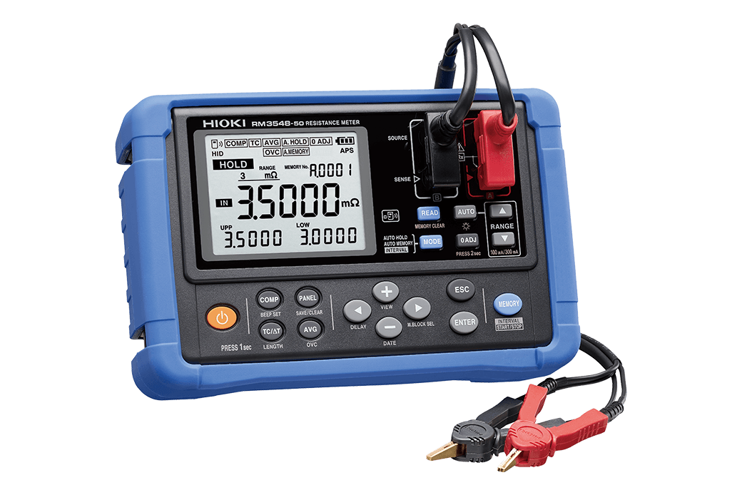
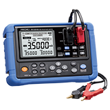
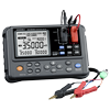
A Convenient Solution in the Hioki RM3548-50 Resistance Meter
The Hioki RM3548-50 Resistance Meter offers both the advanced specifications and portability to carry out these tests quickly and accurately thanks to its 0.0 μΩ to 3.5 MΩ measurement range, 0.1 μΩ resolution and 1 A maximum testing current, more than sufficient to meet the low resistance characteristics demands, very fine resolution and testing current levels.
How to Test
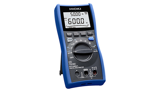
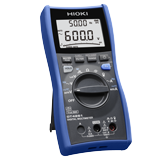
1. Use the Hioki DT4261 Digital Multimeter at its voltage function to test that voltage is not present between exposed conductors and electrical chassis.
2. Set the test current of the 300 mΩ range on the resistance meter to 300 mA (0.3 A).
3. Touch one of the test leads of the resistance meter to the exposed conductive part, and the other to the electrical chassis.
4. Set the resistance meter to the 30 mΩ or 300 mΩ range and maintain the testing current of at least 300 mA.
5. Verify that the resistance reading is not more than 0.1 Ω (100 mΩ) as per the requirements.