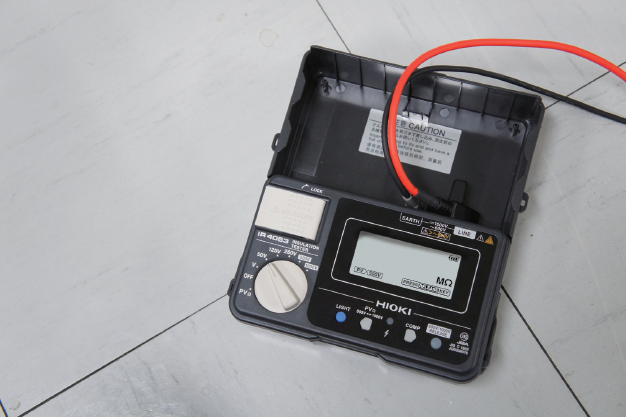
INSULATION TESTER IR4053
Measure PV Insulation Resistance Safely, Accurately and Quickly
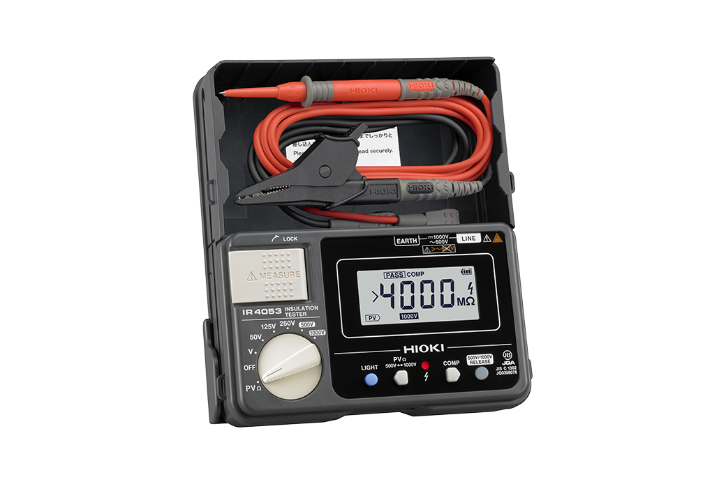
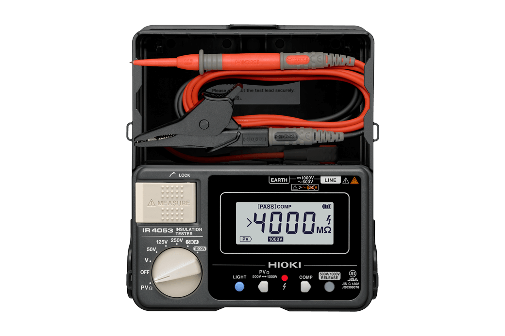
The Hioki IR4053 is a digital insulation resistance tester for photovoltaic generation systems. Measure insulation resistance accurate and safely without being affected by generated solar power and identify the value in just 4 seconds.
CAT III 600 V
Product Video
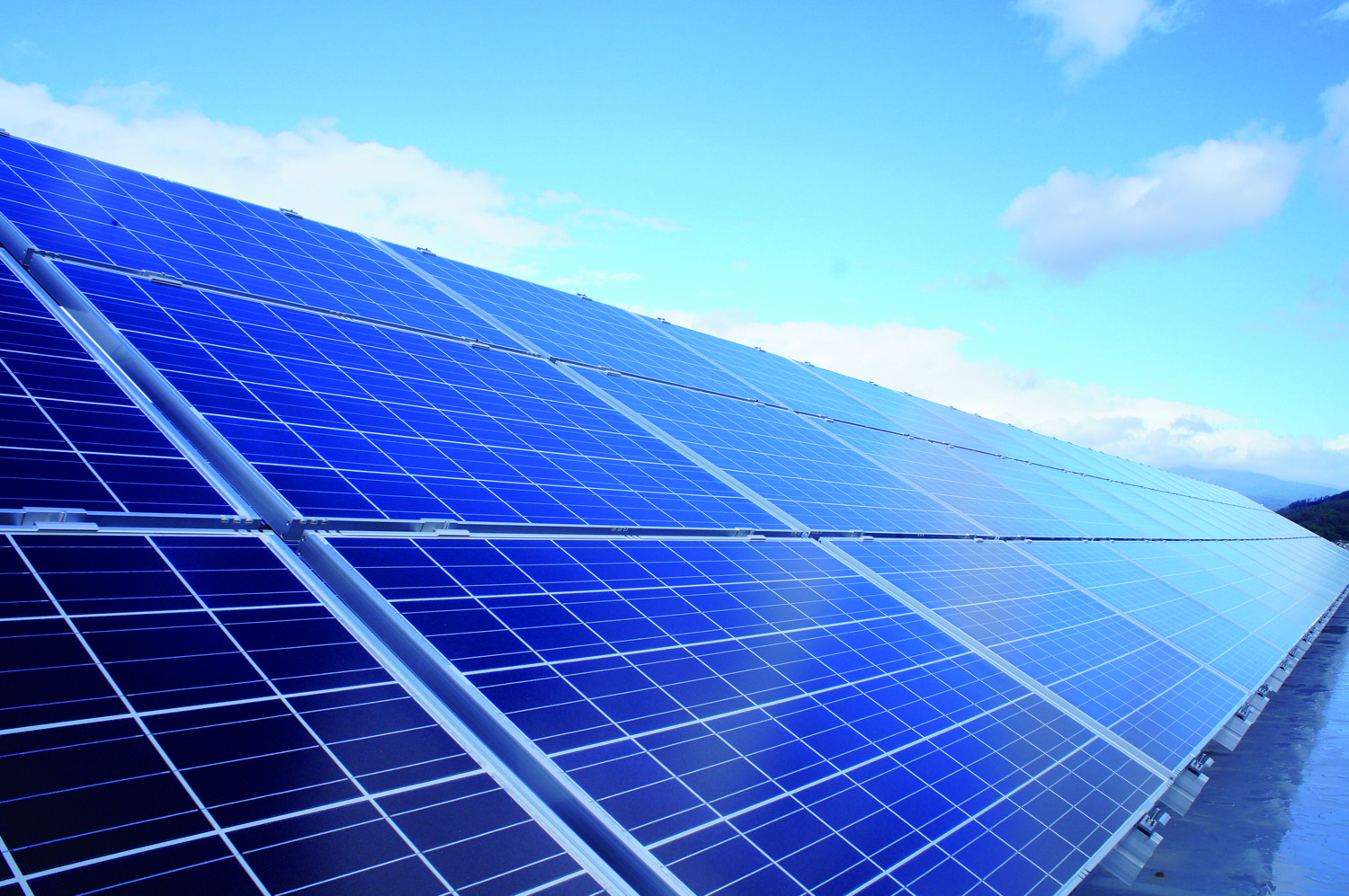
The Hioki IR4053 features a photovoltaic resistance function for measuring solar power systems, allowing you to measure insulation resistance accurately without shorting strings of photovoltaic cells and without risking accidents such as arc discharge events, even as the system continues to generate electricity during daylight hours.
Key Features
- Safely and accurately measure PV insulation resistance even while generating solar power
- Built-in PV dedicated function, display measurements in 4 seconds
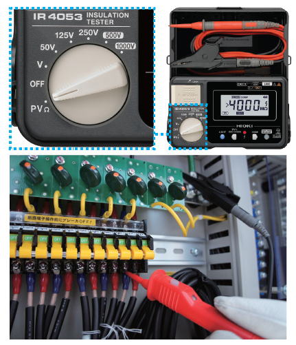
- Five ranges (50/125/250/500/1000V) built in for normal insulation resistance measurement
- Built-in 1000 VDC voltage measurement for open voltage tests of PV systems that support 1000 V
- Built-in comparator function
- Drop proof design withstands drop onto concrete from a height of 1 meter
Model No. (Order Code)
| IR4053-10 | Bundled with Test Lead L9787 |
|---|
Measurement not affected by generating PV
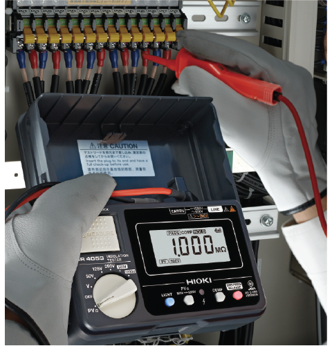
The IR4053, which was designed for PV, can accurately measure insulation resistance without being affected by the generating PV.
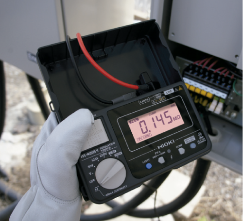
Accurate and safe measurement without creating shorts
Normally, to accurately measure the insulation resistance of a generating PV, one needs to short the measured circuit. With the IR4053's PV measurement mode, short circuiting is not necessary.
Displays measurement in 4 seconds
The IR4053 displays the measured value just 4 seconds after starting measurement. After the first display, the displayed value is updated each second. Comfortably carry out swift measurements.
What are the problems with conventional insulation testers?
Problems with conventional insulation testers and the 2 measurement methods determined by recognized guidelines
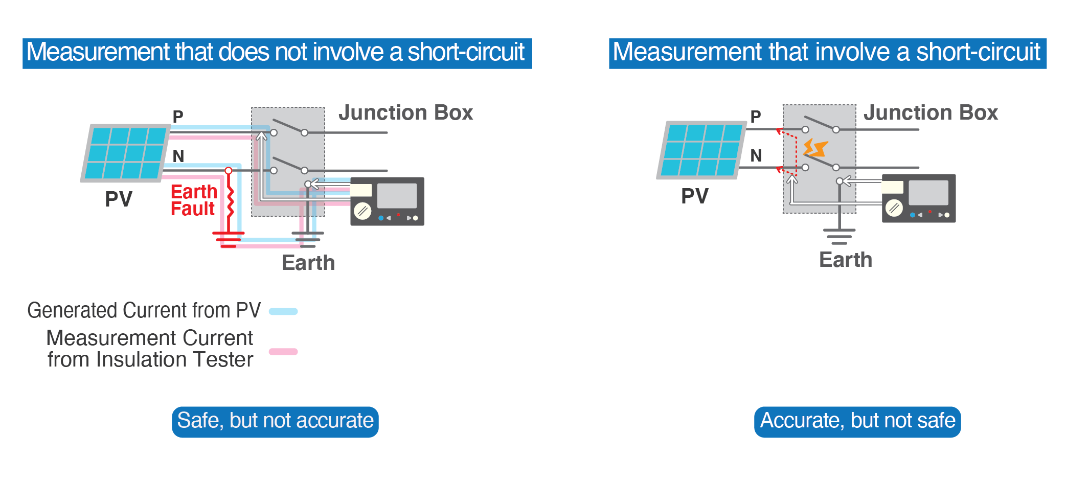
Measurement that does not involve a short-circuit
This is not as dangerous, but depending on the circuit status, the measurement may be affected by the generating PV and may produce a result different from the actual insulation resistance.
Measurement that involve a short-circuit
To accurately measure a generating PV, one needs to short the measured circuit, which requires that a short-circuit switch be separately installed. Short-circuiting will also pose the danger of creating an arc. In addition, to minimize hazards, it is recommended that the testing be conducted at night.
Functions useful in the field
Comparator function/ Red light
You can compare measurements to any set values. If the result does not meet the set value, the red light will warn of nonconformance.
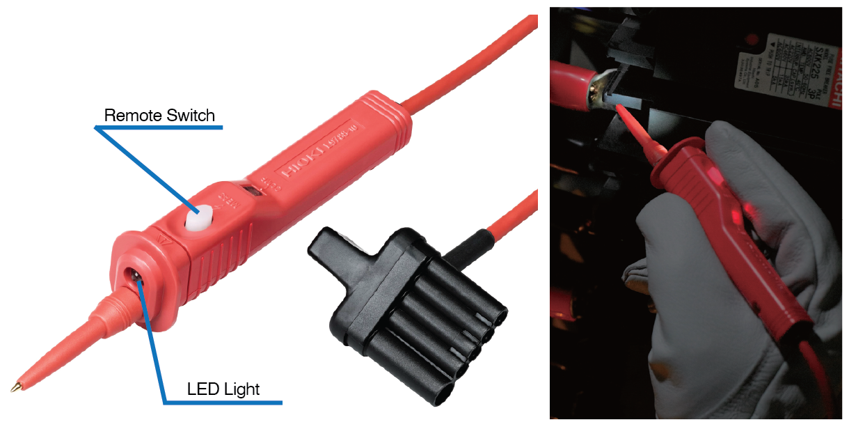
Test lead with remote switch
This allows you to apply output voltage with the switch in your hand, work with a light, and see the result of the comparator with an LED.
Drop proof
The sturdy design will not break even if dropped onto concrete from 1 m, so you
can use it with peace of mind.
Basic specifications: PVΩ measurement
| Rated output voltage | 500 V DC | 1000 V DC |
|---|---|---|
| Effective maximum indicated value | 2000 MΩ | 4000 MΩ |
| Measuring range/ Accuracy | 0.200 to 500 MΩ / ±4% rdg. 501 to 2000 MΩ / ±8% rdg. |
0.200 to 1000 MΩ / ±4% rdg. 1010 to 4000 MΩ / ±8% rdg. |
| Other measuring range / Accuracy | 0 to 0.199 MΩ / ±2% rdg. ±6 dgt. | |
Basic specifications: Insulation resistance measurement
| Rated output voltage | 50 V DC | 125 V DC | 250 V DC | 500 V DC | 1000 V DC | |
|---|---|---|---|---|---|---|
| Effective maximum indicated value | 100 MΩ | 250 MΩ | 500 MΩ | 2000 MΩ | 4000 MΩ | |
| Accuracy 1st effective measuring range MΩ |
±4% rdg. 0.200 to 10.00 |
±4% rdg. 0.200 to 25.0 |
±4% rdg. 0.200 to 50.0 |
±4% rdg. 0.200 to 500 |
±4% rdg. 0.200 to 1000 |
|
| Lower limit resistance | 0.05 MΩ | 0.125 MΩ | 0.25 MΩ | 0.5 MΩ | 1 MΩ | |
| Overload protection | 600 V AC (10 s) | 600 V AC (10 s) | 600 V AC (10 s) | 600 V AC (10 s) | 1200 V DC (10 s) | |
| DC voltage range | 4.2 V (0.001 V resolution) to 1000 V (1 V resolution), 4 ranges, Accuracy: ±1.3% rdg. ±4 dgt., (Ranges in excess of 1000 V are not guaranteed for accuracy.) |
|||||
| AC voltage range | 420 V (0.1 V resolution)/600 V (1 V resolution), 2 ranges, 50/60 Hz, Accuracy: ±2.3% rdg. ±8 dgt., (Ranges in excess of 600 V are not guaranteed for accuracy.) |
|||||
| Display | Semi-transmissive FSTN LCD with back lighting, Backlight | |||||
| Response time | Insulation resistance range: 1 second, PVΩ function: 4 seconds (based on in-house tests) | |||||
| Other functions | Live circuit indicator, automatic electric discharge, automatic DC/AC detection, comparator, drop proof, auto power save | |||||
| Power supply | AA alkaline batteries (LR6) ×4, Continuous operating time: Approx. 20 hours (based on in-house tests) | |||||
| Dimensions and mass | 159 mm (6.26 in) W × 177 mm H (6.97 in) H × 53 mm (2.09 in) D, Approx. 600 g (21.2 oz) (including batteries, excluding test lead) | |||||
| Included accessories | TEST LEAD L9787 ×1, Neck strap ×1, Instruction manual ×1, AA alkaline batteries (LR6) ×4 | |||||
L9788 options (4)
Exclusively for the L9788-10/ L9788-11
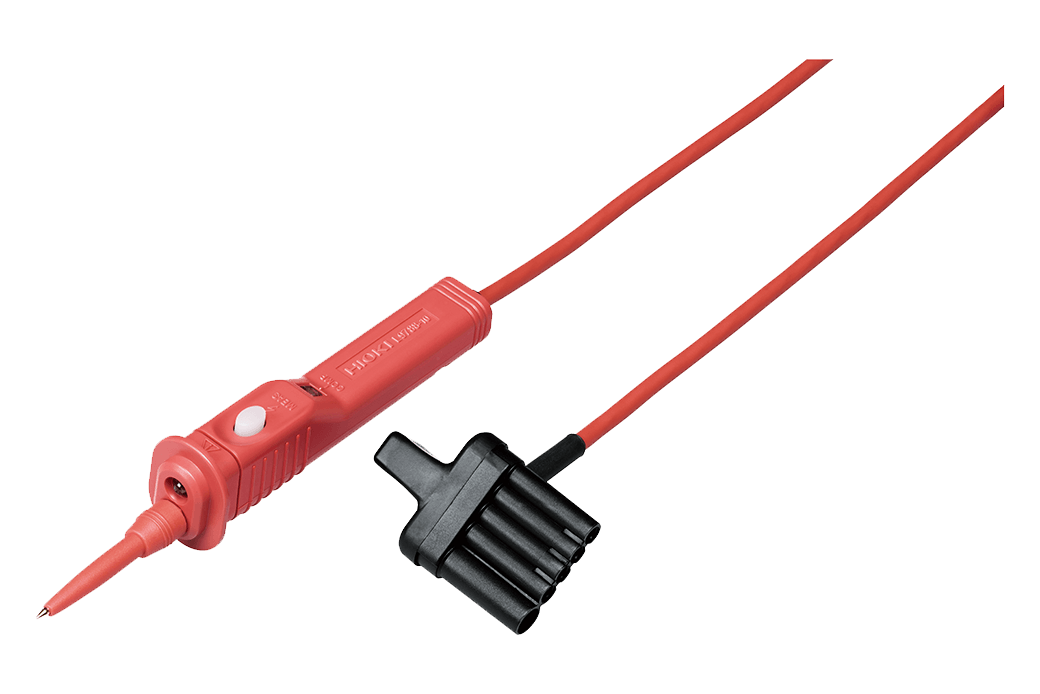
Lighting LED lamp & comparator indicator (Operate only when main unit provides a comparator function), 1.2 m (3.94 ft.) length
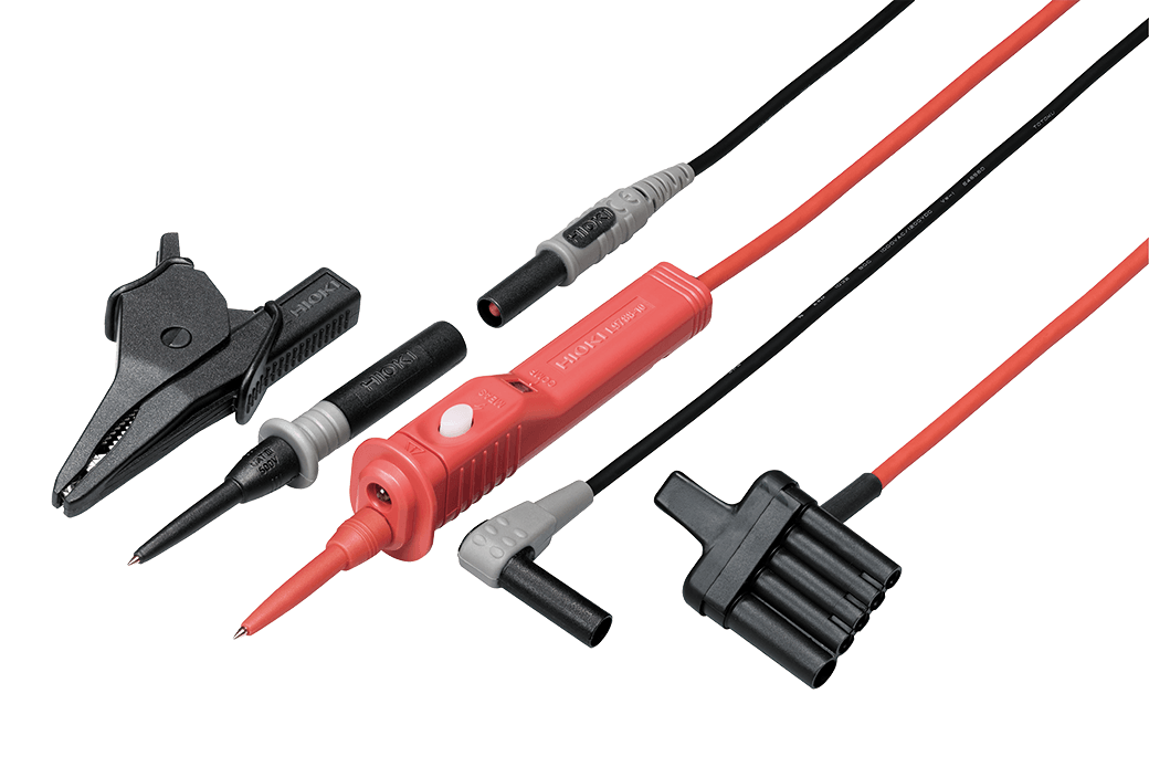
Bundled with Test Lead with Remote Switch L9788-10/ Earth lead, alligator clip, 1.2 m (3.94 ft) length
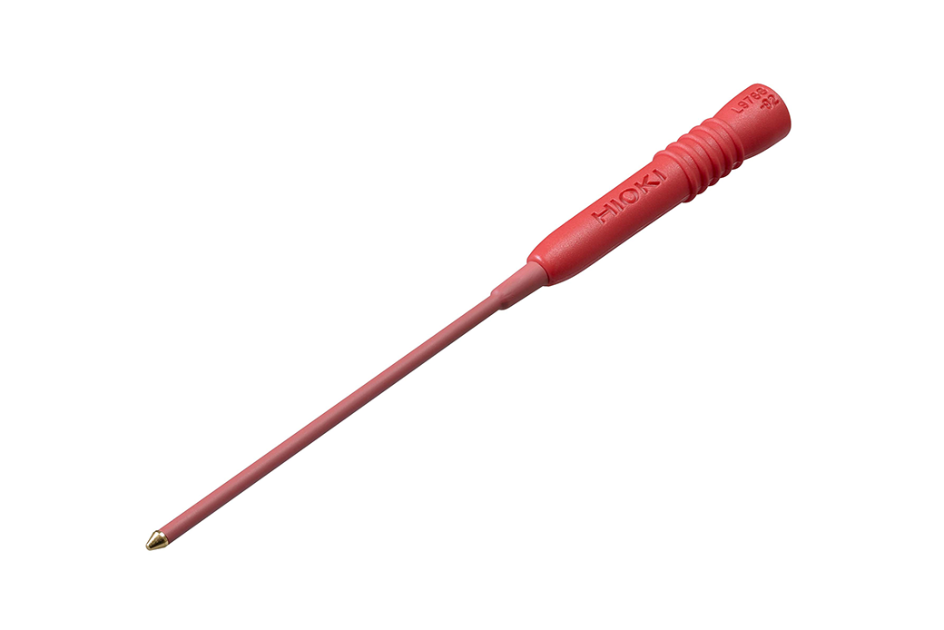
Spare parts for tip of the L9788/ L9788-10, Tip length 35 mm (1.38 in.)/φ 3.2 mm (0.13 in.)
For checking breaker terminal, Detachable for tip of the L9788-10, 65 mm (2.56 in) length, φ 2.6 mm (0.10 in)
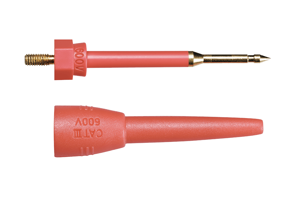
L9787 options (2)
Exclusively for the L9787 *The L9787 is bundled
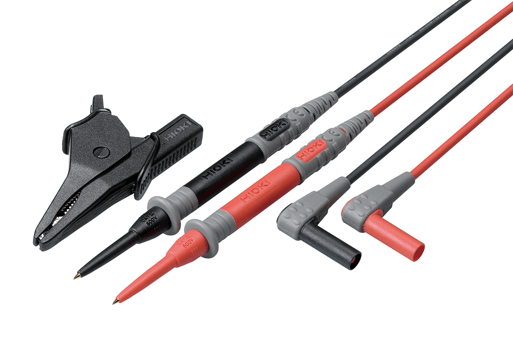
Bundled with alligator clip, 1.2 m (3.94 ft) length
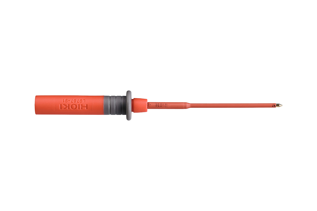
For checking breaker terminal, Detachable for tip of the L9787, 48 mm (1.89 in) length, φ 2.6 mm (0.10 in)
Shared Option (1)
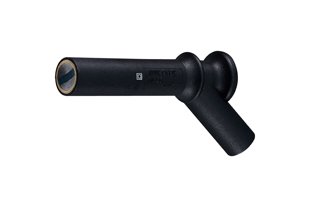
Attaches to the tip of cord, black ×1, φ11 mm (0.43 in.)
Replacement Parts (6)
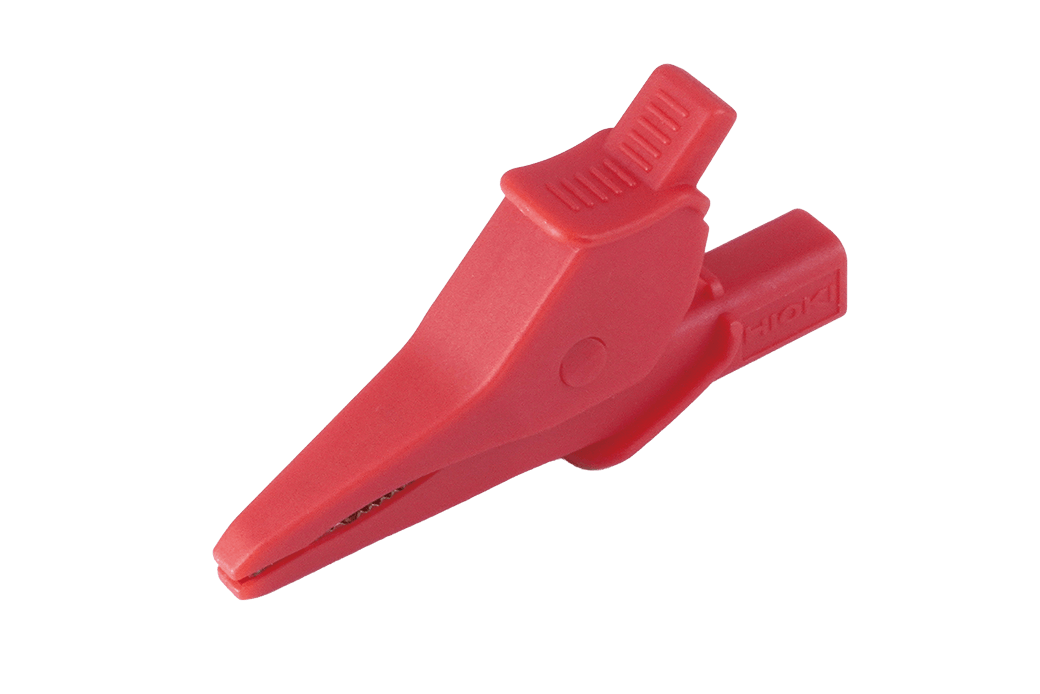
Order Code: Z7025
Replacement part for the red alligator clip of the product listed below:
L1000, L1000-05, L2200, L4935, L9197, L9257, L9438-50, L9438-53, L9787, L9844, P9000
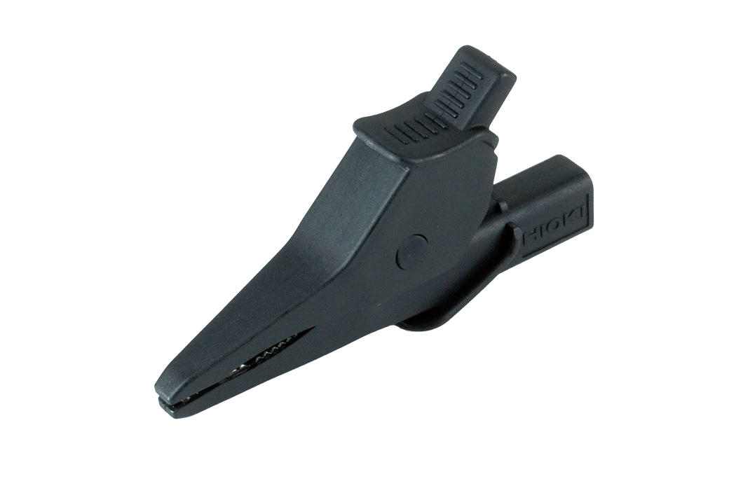
Order Code: Z7026
Replacement part for the black alligator clip of the product listed below:
L1000, L1000-05, L2200, L4935, L9197, L9257, L9438-50, L9438-53, L9787, L9788-11, L9844, P9000, SP7100, SP7150
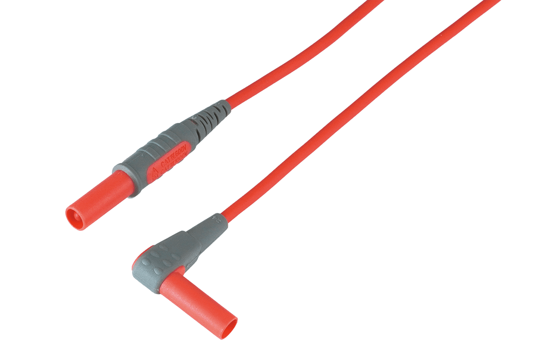
Order Code: Z7027
Replacement part for the red test lead of the product listed below:
L4930, L9257, L9787, L9844
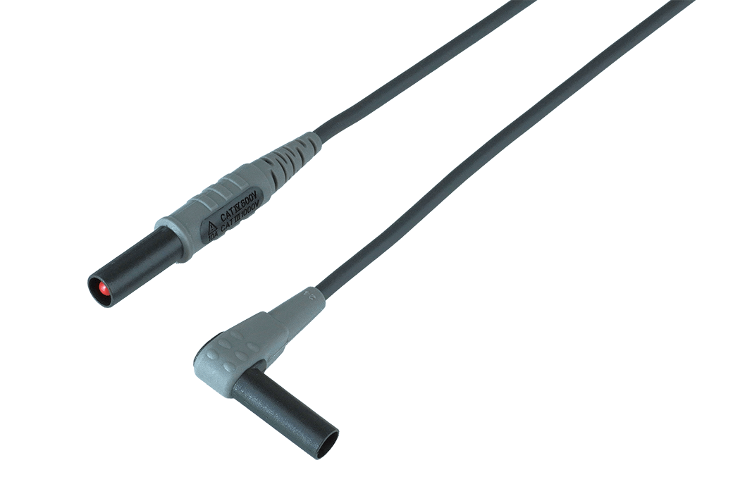
Order Code: Z7028
Replacement part for the black test lead of the product listed below:
L4930, L9257, L9787, L9788-11, L9844
Order Code: Z7029
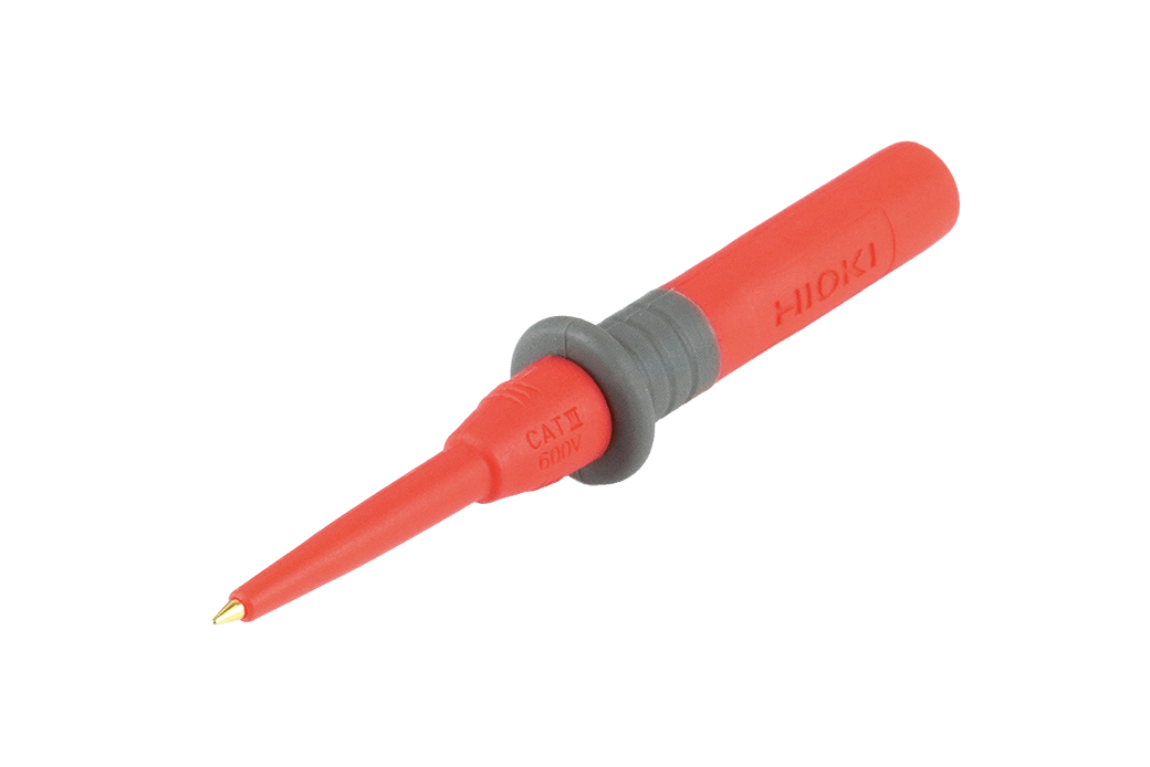
Replacement part for the red test pin of the product listed below:
L2200, L4938, L9787
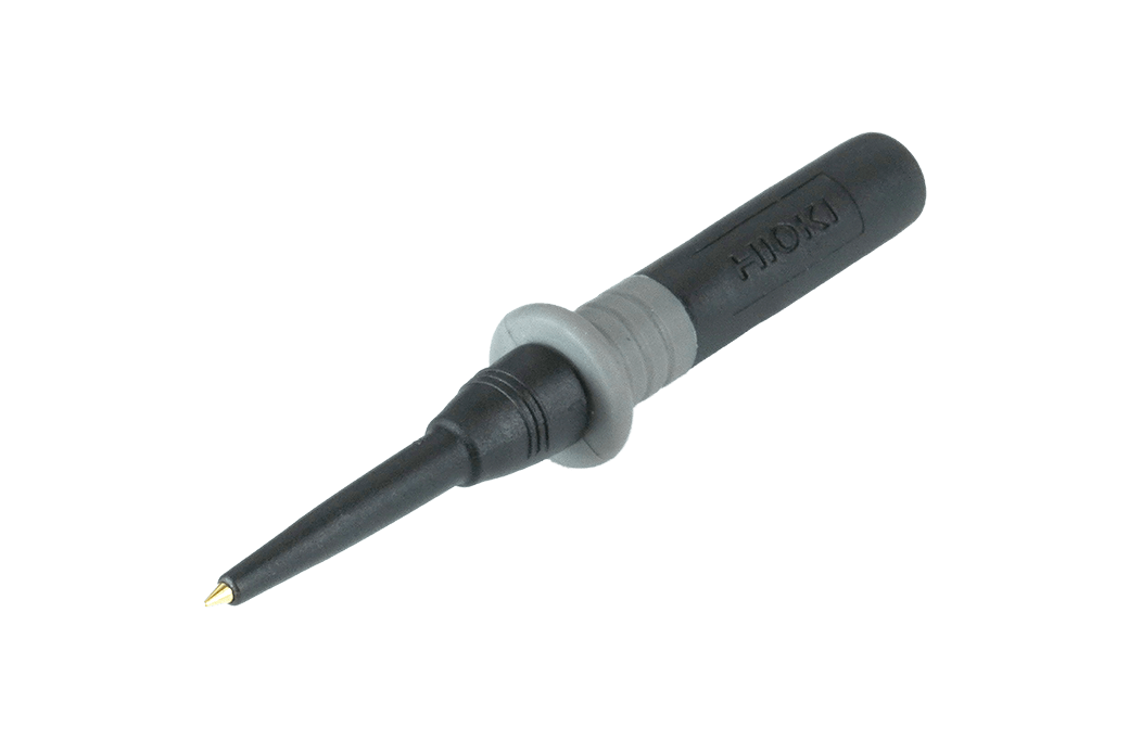
Order Code: Z7030
Replacement part for the black test pin of the product listed below:
L2200, L4938, L9787, L9788-11
-
INSULATION TESTER IR4053-10, IR4053-11
 Test Report
Japanese
Test Report
Japanese
English Ver.01 -
INSULATION TESTER IR4053-10, IR4055-11, IR4056-20, IR4056-21, IR4057-50
Instruction Manual
English
Ver.02
-
INSULATION TESTER IR4051-10, IR4052-50, IR4052-51, IR4053-10, IR4056-20, IR4056-21, IR4057-50
Instruction Manual
Korean
Ver.03
-
INSULATION TESTER IR4053-10, IR4056-20, IR4056-21, IR4057-50
Instruction Manual
Simplified Chinese
Ver.02
-
INSULATION TESTER IR4053-10, IR4056-20, IR4057-50
Instruction Manual
French
Ver.02
-
INSULATION TESTER IR4053-10, IR4056-20, IR4057-50
Instruction Manual
German
Ver.02