RFID (Contactless IC cards, Contactless IC tags)
How are RFID regulated?
The operating frequencies of RFIDs, which are also known as IC tags or contactless IC cards, are defined by international standards. When performing L measurement of a board used by a contactless IC card, the measurement must be made near the operating frequency of 13.56 MHz.
Setting example of measurement conditions
| Measurement mode | ANALYZER | |||||||||||||||||||||||||||
| Parameters | Z-θ frequency characteristics analysis(L-Q、R evaluation available) | |||||||||||||||||||||||||||
| Sweep parameter | FREQ | |||||||||||||||||||||||||||
| Sweep frequency | Sweep measurement close to the operating frequency (See the table below) | |||||||||||||||||||||||||||
| Signal level | V mode 1V (350x, IM35xx series) or 1dBm (IM758x series) | |||||||||||||||||||||||||||
RFID standards
| Category | Frequency | Effective distance | Standard | ||||||||||||||||||||||
| ID cards | 13.56MHz | Up to 10cm (Proximity applications) | ISO 14443 | ||||||||||||||||||||||
| Automatic recognition | 125kHz | Up to 70cm (Vicinity applications) | ISO 14443 | ||||||||||||||||||||||
| 13.56MHz | ISO 15693 | ||||||||||||||||||||||||
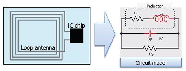
Structure of RFID tags
RFIDs generally consist of an antenna and IC. Signal transmission is accomplished by a resonant circuit formed by the antenna inductor (Ls) and the IC chip’s built-in input capacitance (Cp).
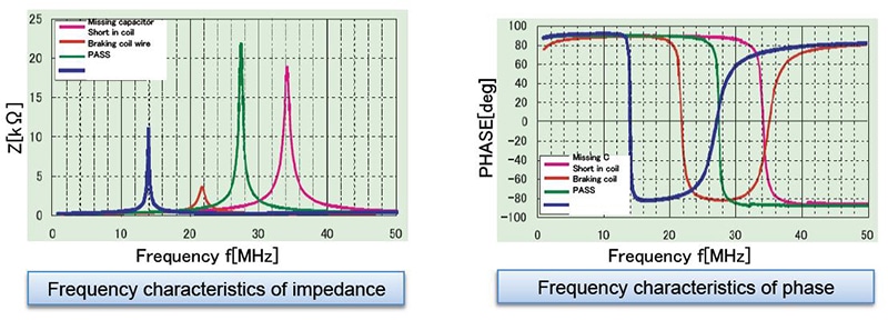
Frequency characteristics of defective and non-defective components
As shown in the figures, the Z-θ frequency characteristics of defective and non-defective components differ. The non-defective component exhibits a resonance point near the operating frequency.
Instruments for Research & Development Applications
| Model | Measurement frequency | RFID | ||||||||||||||||||||||||||||
| IM758x series | 100k to 1.3GHz * | Mainly for high-frequency RFID | ||||||||||||||||||||||||||||
| IM3570 | 4Hz to 5MHz | Mainly for low-frequency to medium frequency RFID | ||||||||||||||||||||||||||||
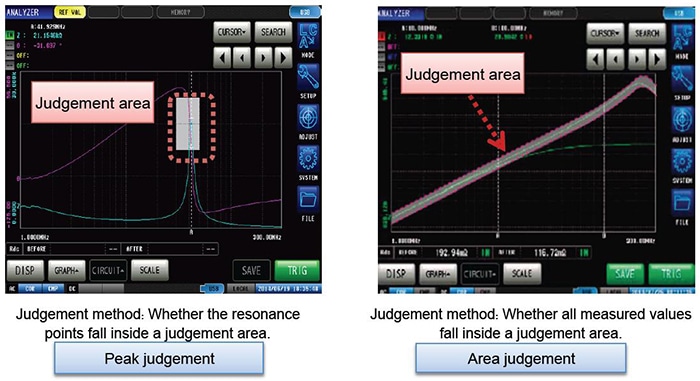
Pass/fail judgments using analyzer mode
Either of two methods can be used to generate pass/fail judgments when using analyzer mode: peak judgment and area judgment.
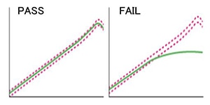
How to set the judgment area
Judgement areas can be set as follows.
• A known-good element’s measured value can be used as the reference (±10% of the reference element’s measured value, etc.).
• A user-specified value can be entered (1 k±10%, etc.).
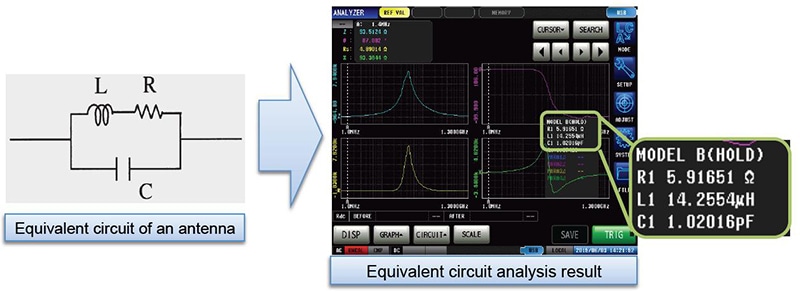
Ascertaining electrical constants by means of equivalent circuit analysis
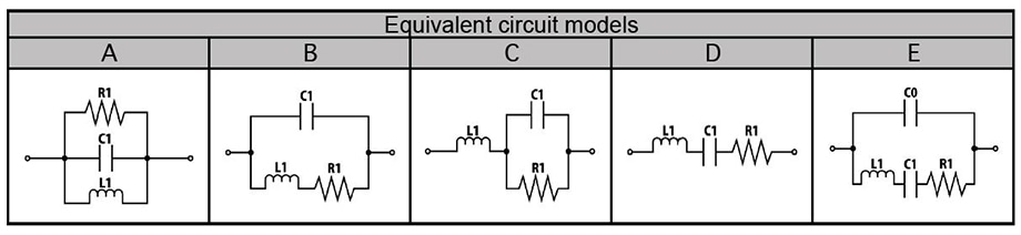
The instrument’s equivalent circuit analysis function can be used to calculate the constants in a three-terminal circuit model such as an RFID antenna.
*Model A should be used for coils with a large core loss (R) in order to facilitate more accurate analysis.