How to use insulation testers
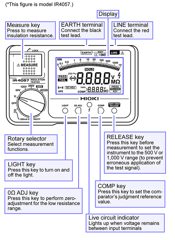
Components of an insulation tester
The figure illustrates the name of each part of the Hioki Insulation Tester IR4057.
Insulation resistance measurement
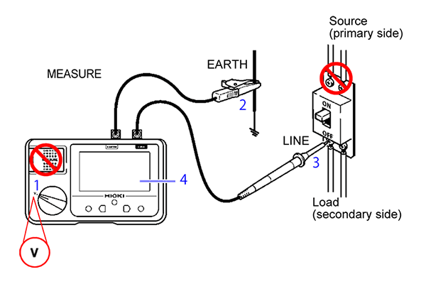
Warning: Do not attempt to measure insulation resistance on a live conductor.
・ Verify that the MEASURE key is not in the raised position ([1] in the figure).
・ Consult the table and determine the measurement voltage to which to set the rotary switch ([2] in the figure).
・ Connect the black test lead to the ground side of the object being measured. [3]
・ Connect the red test lead to the line to be measured. [4]
・ Press the MEASURE key. [5]
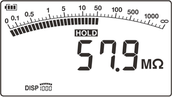
・ Read the value after the inductor has stabilized. [6]
*This list provides an overview of how to use insulation testers. Please consult the user manual for your product to ensure safe and proper use.
*Please note that values in the table apply to testing in Japan.
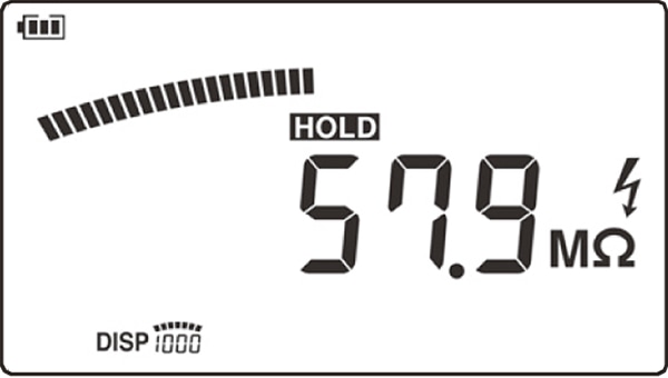
Discharging function
To properly discharge, be sure to perform as shown below after the measurement.
・ Without removing the test leads from the item being measured, release the MEASURE key.
・ The built-in discharge circuit automatically discharges the item.
・ The discharge will end when the “discharge mark” on the right side of the display disappears.
*This list provides an overview of how to use insulation testers. Please consult the user manual for your product to ensure safe and proper use.
*Please note that values in the table apply to testing in Japan.
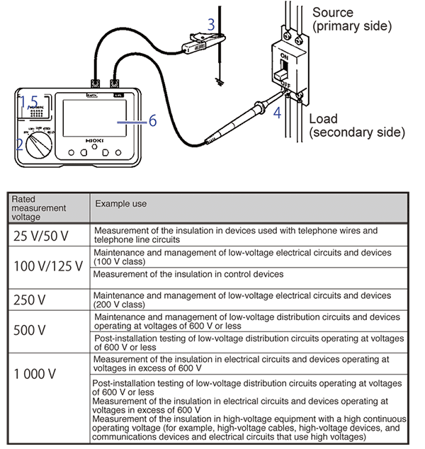
Voltage measurement
Notes: Test leads should only be connected to the secondary side of a breaker.
Never press the MEASURE key while measuring voltage.
・ Use the rotary selector to select the V function.
・ Connect the black test lead to the ground side of the object being measured.
・ Connect the red test lead to the line side of the breaker.
・ Read the value after the indicator has stabilized.
*This list provides an overview of how to use insulation testers based on the Hioki Model IR4057. Please consult the user manual for your product to ensure safe and proper use.
*Please note that values in the table apply to testing in Japan.
Resistance measurement
Before measurement, perform zero adjustment to cancel the test leads’ wiring resistance and other potentially problematic quantities.
・ Set the rotary selector to the Ω function.
・ Short circuit the tip of the test lead.
・ Pull up the MEASURE key.
・ Turn off the MEASURE key to hold the measured value.
・ Press the “0Ω ADJ” key.
・ Connect the test lead to the ground side of the object being measured
・ Press MEASURE key and read the displayed value.
・ Turn off the MEASURE key after using.
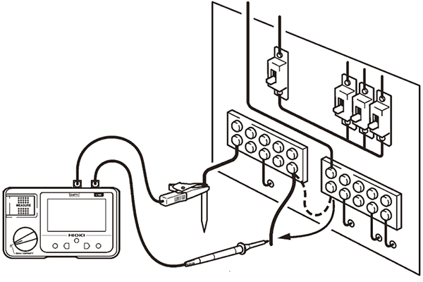
The figure is an example of checking the continuity of ground wiring.
*This list provides an overview of how to use insulation testers based on the Hioki Model IR4057. Please consult the user manual for your product to ensure safe and proper use.
*Please note that values in the table apply to testing in Japan.
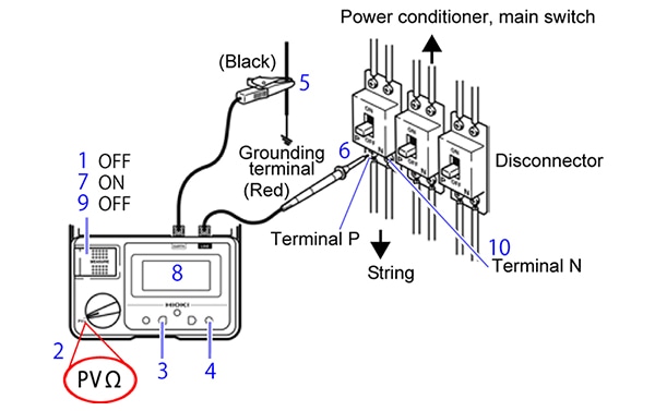
PVΩ measurement (Insulation Tester IR4053 only)
PVΩ measurement is used to measure insulation resistance between a solar panel and ground. The PVΩ measurement allows accurate resistance measurements without the effect from power generation.
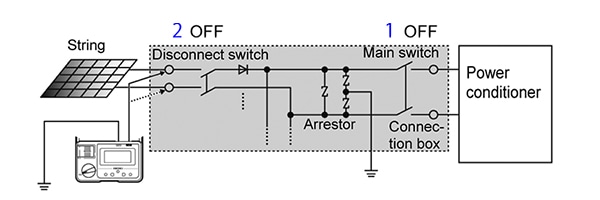
・ Turn OFF the main switch to the connection box to be discontinued from the power conditioner.
・ Turn OFF all disconnect switches used for strings.
・ Check that MEASURE key has been turned OFF. [1]
・ Set the rotary switch to “PVΩ".
・ Press the PVΩ 500V⇔1000V key and set the voltage to 500 V or 1000 V. [3]
・ Press the “500V/1000V RELEASE” key to release the lock. [4]
・ Connect the black test lead to the ground terminal. [5]
・ Connect the red test lead to terminal P of the string. [6]
・ Press the MEASURE key. [7]
・ A resistance will be indicated after approximately four seconds. [8]
・ Turn OFF the MEASURE key. [9]
・ If there is no deteriorated insulation performance found with terminal P measurement, connect the red test lead to the terminal N of the string to measurements by procedures from [7] through [9].
*This list provides an overview of how to use insulation testers based on the Hioki Model IR4053. Please consult the user manual for your product to ensure safe and proper use.
*Please note that values in the table apply to testing in Japan.