Using a ground resistance tester: Measurement principles and reference resistance values
What is a ground resistance tester?
The resistance between a grounding electrode and the earth is generally known as ground resistance. More precisely, ground resistance is the total of the grounding conductor’s resistance, the contact resistance of the grounding conductor and earth, and the earth’s resistance. Ground resistance differs from ordinary resistors in that it has the following special characteristics:
• Polarizing action
Because the earth behaves like an electrolyte, it exhibits polarizing action such that a DC current produces electromotive force in the opposite direction, making accurate measurement impossible. Consequently, ground resistance is generally measured using a square wave or sine wave at a frequency of several dozens of hertz to 1 kHz.
• Special measurement setup
Ground resistance is the resistance between a grounding electrode and the earth. It cannot be measured without inserting the electrode into the ground. Since earth has comparatively low resistivity, a voltage drop occurs near the electrode from which the current used to make the measurement flows. Consequently, in order to accurately measure the resistance value of each grounding electrode (the E electrode, S [P] electrode, and H [C] electrode), you must move about 10 m away.
• Existence of disturbances
Measurement of ground resistance is subject to disturbances such as ground potential and the effects of the auxiliary grounding electrodes. Ground potential caused by leakage current from devices connected to the grounding electrode is superposed on the signal that the ground resistance tester detects, affecting measured values. In addition, if the auxiliary grounding electrodes have a high ground resistance, the measurement current will decrease, making measurement more susceptible to the effects of noise such as ground potential.
The FT6031 is designed to be resistant to these external effects, allowing accurate measurement even under poor conditions.
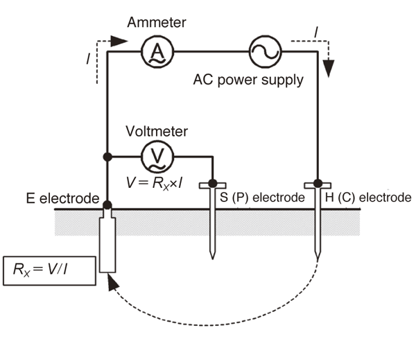
Ground resistance tester measurement principles
An AC power supply’s voltage is applied between the H (C) and E electrodes, and the AC current I that flows as a result is measured by an ammeter. In addition, the voltage V that occurs between the S (P) and E electrodes when the current I flows is measured using an AC voltmeter.
Then the ground resistance RX of the E electrode is calculated from the measured current I and voltage V. It is not possible to accurately measure the voltage between the H (C) and E electrodes, or the voltage between the H (C) and S (P) electrodes.
Types of grounding installations and grounding reference resistance values
The Technical Standards of Electric Installation set forth the following grounding installation types and ground resistance values*1:
Grounding installation Ground resistance value
Class A (formerly Class 1) 10 Ω or less
Class B (formerly Class 2) Calculated value*2
Class C (formerly Class 3) 10 Ω or less*3
Class D (formerly class 3) 100 Ω or less*3
*1 The values from Japanese standards are listed.
Please note that these values vary by country.
*2 Ohm value equivalent to the result of dividing the ground-fault current in amperes of one wire in the circuit on the high-voltage or special-high-voltage side of the transformer by 150 (or, if the low-voltage circuit’s voltage to ground exceeds 150 V due to the combination of the circuit on the low-voltage side of the transformer with [a] the circuit on the high-voltage side of the transformer or [b] a circuit on the special-high-voltage side with a service voltage of 35,000 V or less, by either [1] 300, if equipped with a device that will automatically shut off the high-voltage circuit or special-high-voltage circuit with a service voltage of 35,000 V or less in more than 1 but less than 2 seconds, or [2] 600, if equipped with a device that will automatically shut off the high-voltage circuit or special-high-voltage circuit with a service voltage of 35,000 V in less than 1 second)
*3 If equipped with a device that will automatically shut off the the low-voltage circuit in question within 0.5 seconds in the event of a ground fault, 500 Ω