Clamp meter functions and how to use them
Current measurement
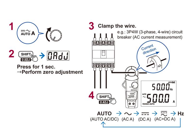
• Set the rotary switch as shown in “1”.
• Enable zero-adjustment as shown in “2”.
• Apply the clamp meter around the wire as shown in “3”.
• Determine the function as appropriate from auto, AC current, DC current, AC+DC current, or frequency as shown in “4”.
*This example uses the Clamp Meter CM4370 series.
HOLD function
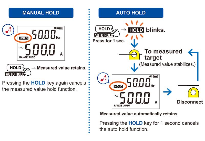
MANUAL HOLD:
• The measured value on the display can be held by pressing the HOLD key.
AUTO HOLD:
• Press and hold the HOLD key for 1 sec. to enable the auto hold function.
• Once the measured value stabilizes, it will be automatically held as shown in the figure.
• The measured value will continue to be held once the clamp is removed from the wire.
• Once you apply the clamp meter around another wire and the measured value stabilizes, it will be automatically held again.
• This function is convenient when you need to make and record results for a series of measurements.
*This example uses the Clamp Meter CM4370 series.
Filter function
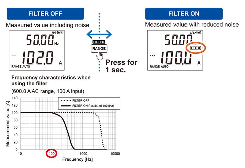
• The filter can be applied based on a 100 Hz cutoff frequency.
• This function is convenient when you wish to measure the current value near the power supply frequency without being affected by noise or other interference.
*This example uses the Clamp Meter CM4370 series.
MAX/MIN/AVG/PEAK
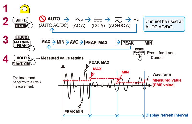
• The MAX/MIN/AVG function records the maximum, minimum, and average values for the measured value (RMS) interval being displayed.
• The peak max and peak min functions display the maximum and minimum values of current waveform peaks after 10 kHz sampling.
*This example uses the Clamp Meter CM4370 series.
DC current and DC voltage PEAK measurement
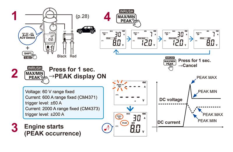
• Apply the clamp around the wire coming from the vehicle battery’s positive terminal as shown in “1” in the figure and set the rotary switch as shown in the figure.
• Operate the control key as shown in “2” in the figure.
• Start the vehicle’s engine.
• By performing the steps shown in “4” in the figure, you can read the maximum and minimum values for the instantaneous DC current when the engine is started as well as the DC voltage maximum and minimum values.
*This example uses the Clamp Meter CM4370 series.
Inrush current measurement (INRUSH)
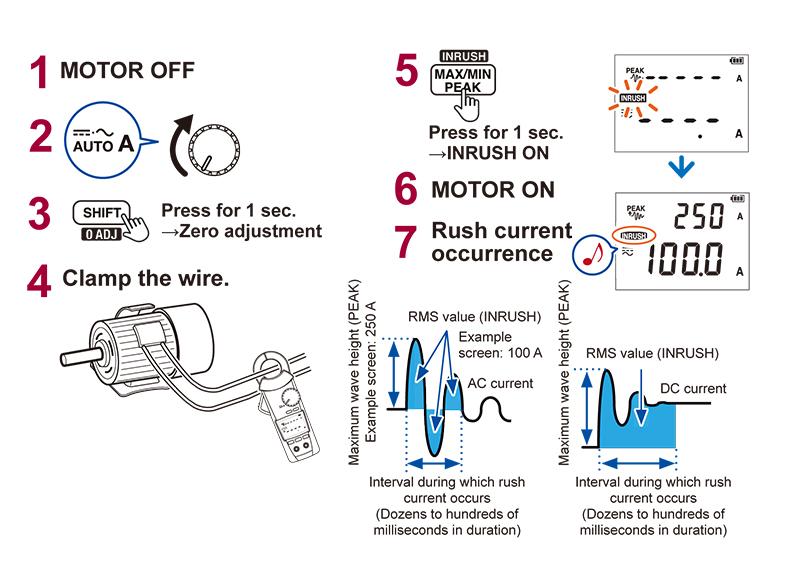
• Disconnect the power supply of the motor or other load.
• Determine the appropriate position for the rotary switch as shown in “2” in the figure.
• Perform zero-adjustment as shown in “3” in the figure.
• Apply the clamp around one of the load circuit’s wires as shown in “4” in the figure.
• Enable the INRUSH function as shown in “5” in the figure.
• Start the motor or other load.
• As shown in “7” in the figure, you can read the peak (maximum peak value) and RMS value for the interval during which the inrush current (starting current) occurs.
*This example uses the Clamp Meter CM4370 series.
Other measurement functions: Voltage measurement
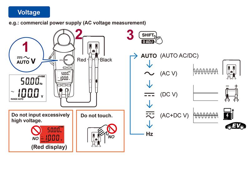
• Connect the measurement leads to the clamp meter.
• Set the rotary switch to voltage measurement as shown in “1” in the figure.
• Place the measurement leads in contact with the point you wish to measure as shown in “2” in the figure.
• Select the desired function (auto, AC voltage, DC voltage, AC+DC voltage, or frequency) as shown in “3” in the figure.
*This example uses the Clamp Meter CM4370 series.
Other measurement functions: Continuity check, Resistance, Diode
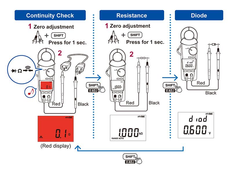
• Set the rotary switch to the position shown in the figure.
• Using the SHIFT key, you can check continuity or perform resistance or diode measurement.
*This example uses the Clamp Meter CM4370 series.
Other measurement functions: Capacitance, Temperature
• After setting the rotary switch to TEMP, you can use the SHIFT key to perform capacitance or temperature measurement.
*This example uses the Clamp Meter CM4370 series.
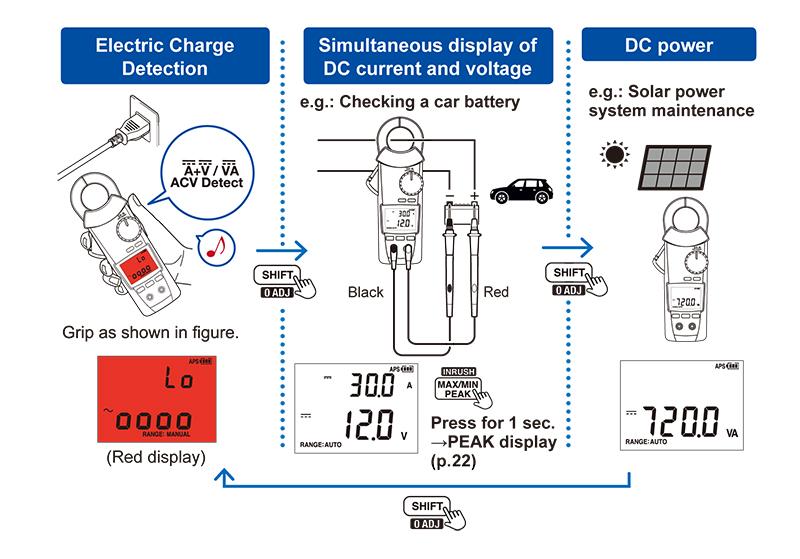
Other measurement functions: Electric charge detection, Simultaneous display of DC current and voltage, DC power
After determining the rotary switch position as shown in the figure, you can use the SHIFT key to detect a voltage, simultaneously display DC current and voltage, or measure the DC power being produced by a solar power system.
*This example uses the Clamp Meter CM4370 series.

