To inverter/motor developers focusing on a 0.1% efficiency improvement
Energy efficiency improvement is a critical issue for achieving a sustainable society, particularly in the context of technologies that drive our daily lives. Inverters and motors are indispensable in various fields, including industrial machinery, transportation, and household appliances. The performance of these inverters and motors running in various facets of our lives directly impacts society’s overall energy consumption. To maximize their efficiency and minimize energy conversion losses, repeatable measurements, precise problem identification, and the effective use of measurement data are essential.

In this application note, we explore the challenges encountered by industry leaders in their efforts to improve conversion efficiency and present solutions that utilize Hioki's high-precision power analyzers to address these challenges.
1. The challenges faced by industry-leading users
The discrepancy between simulation and actual measurement values
01. Measurement inaccuracy
Incorrect pass/fail judgment result in inaccurate simulation-based development.
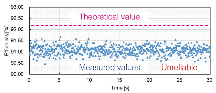
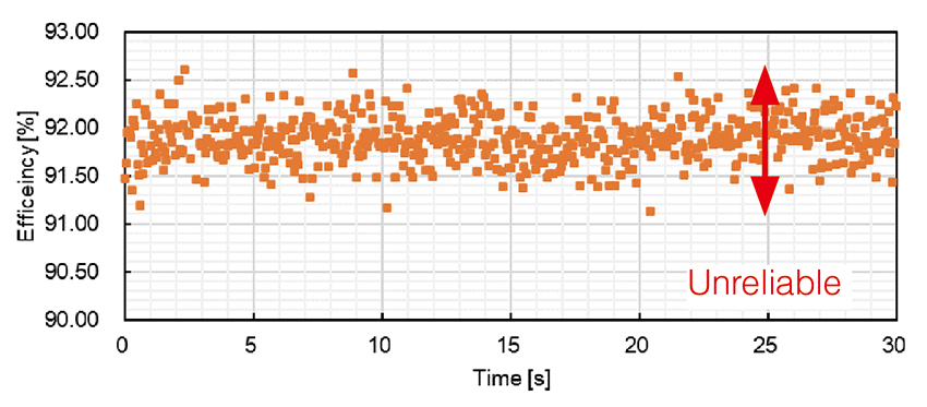
The measured values exhibit significant variability
02. Time-consuming
To minimize variation, lengthy data averaging is necessary. However, this results in a substantial increase in cooling time as motor temperature rises in the process.
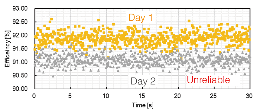
The measurement results differ depending on the location and day
03. Reproducibility
Without data reproducibility, correct design improvement assessment is hindered, preventing high-quality outcomes.
2. What is the reason?
When examining the inverter voltage and current waveforms...
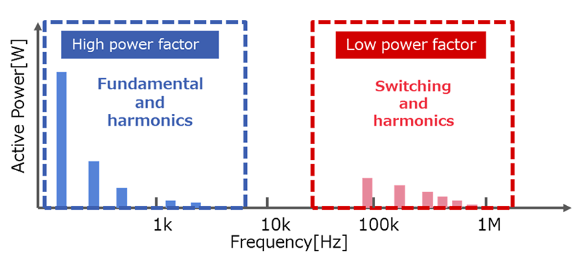
The output power of the inverter includes the fundamental frequency component driving the motor, its harmonics (blue spot), the inverter switching frequency and its harmonics (red point). Since the fundamental wave and its harmonic components are low frequency band of several kHz, it is possible to measure it accurately with the general power meter and current sensor. However, since the switching frequency and its harmonic components become high frequency bands of low frequencies of several tens of kHz to several MHz and low power factor, it requires a power meter and a current sensor which can be measured in the wideband to the phase accurately. In inverter development, accurate measurement of high frequency power is key.
3. Attention !!
The solution only Hioki can provide
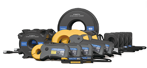
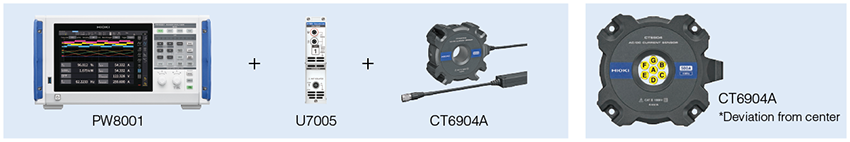
Hioki: Uniquely Tailoring Power Analyzers and Current Sensors for Optimal Performance
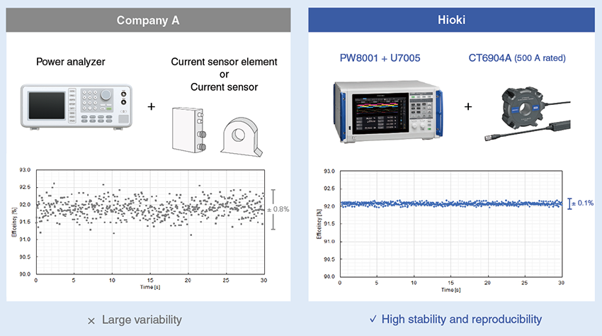
Hioki’s power analyzers are used with a lineup of dedicated current sensors. Because both are developed in-house, you can achieve highly repeatable measurements that are not possible by other brands without this advantage. Pursuing efficiency improvement in inverters requires highly repeatable measurement of high-frequency power. By utilizing fine-tuned frequency characteristics of the sensors, our power analyzer can perform unparalleled phase correction, making remarkably stable measurements and delivering accuracy and reproducibility.
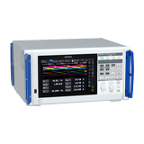
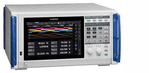
Power Analyzers PW8001
Accuracy: 0.03% (50/60 Hz)
Bandwidth: DC to 5 MHz
Automatic phase correction for our current sensors
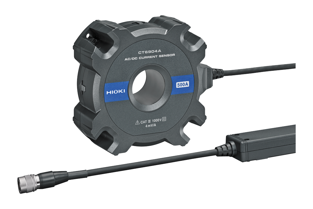
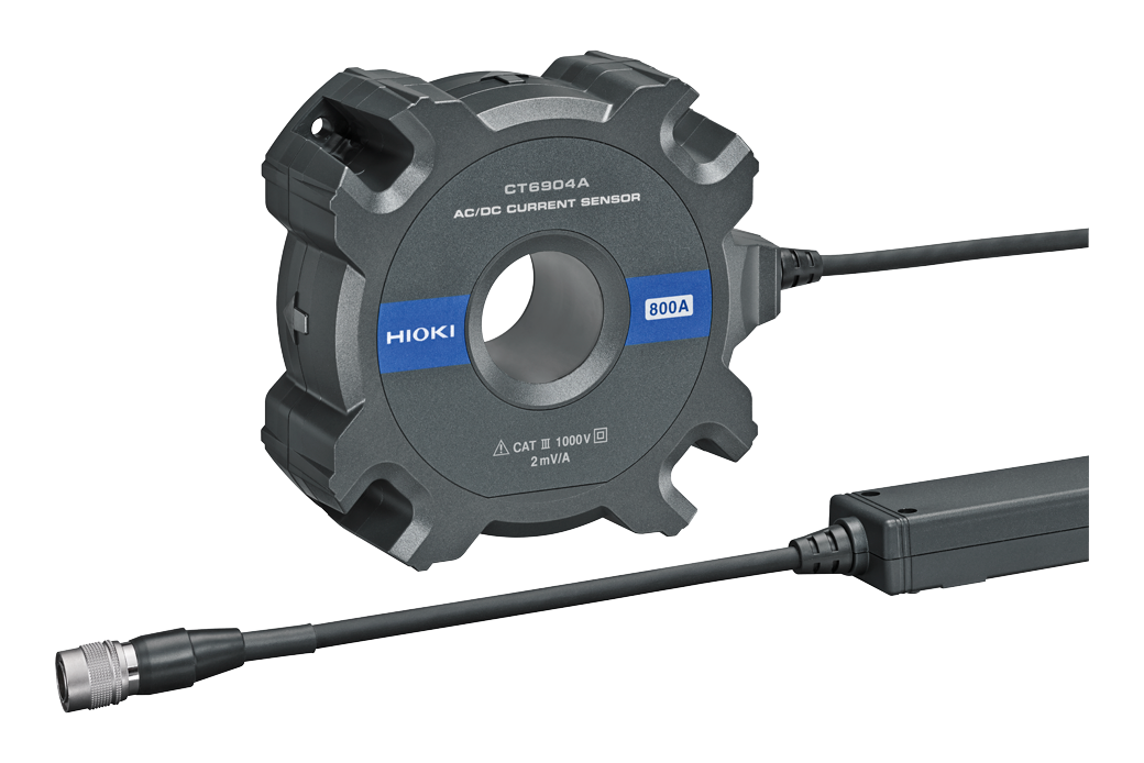
High-accuracy current sensors
Rated Current: 2 to 2000 A
Bandwidth: DC to10 MHz
World-class accuracy & bandwidth
High noise immunity and reproducibility
4. Explanation
3 reasons why PW8001 can accurately measure high-frequency power
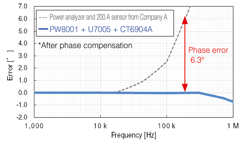
Comparison of phase error
01. Accuracy
Typical power analyzers
Accurate measurement of highfrequency power is not possible due to significant phase errors at high frequencies,.
Hioki’s PW8001 and current sensors
Precise high-frequency phase correction is uniquely possible because we develop current sensors in-house, enabling us to fully understand their characteristics.
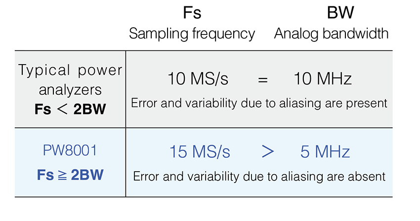
Effect of aliasing
02. Stability
Typical power analyzers
Aliasing error occurs due to insufficient sampling frequency (Fs) relative to analog bandwidth (BW).
Hioki’s PW8001 and current sensors
We achieve simultaneous wideband measurements up to 5 MHz and prevent aliasing by employing a high-speed 15 MHz sampling A/D converter.
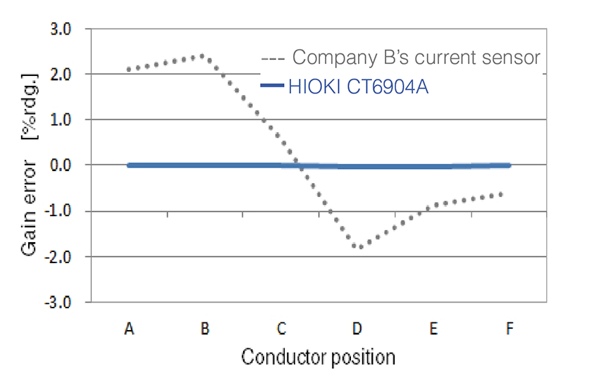
Effect of conductor position (100 kHz)
03. Reproducibility
Typical current sensors
Conductor position changes measurement values, especially at higher frequencies.
Hioki’s PW8001 and current sensors
Measurements are unaffected by conductor position thanks to unique techniques in coil winding arrangements and shielding.
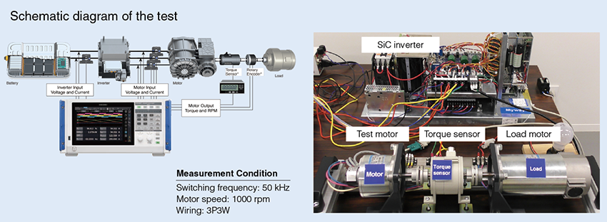
5. Efficiency measurement results of SiC inverters
For more details
PW8001 introduction https://www.hioki.com/sg-en/products/power-meters/power-analyzer/id_412384
Technical paper https://www.hioki.com/sg-en/download/31462
PW8001 introduction video https://www.youtube.com/watch?v=Sr7W8Da2efY&t=7s