NON-CONTACT CAN SENSOR SP7001, SP7002
Easy CAN Acquisition
Simply Pinch Over Wire Insulation
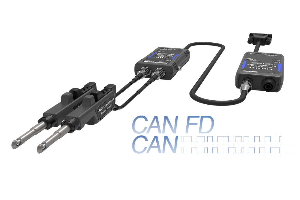
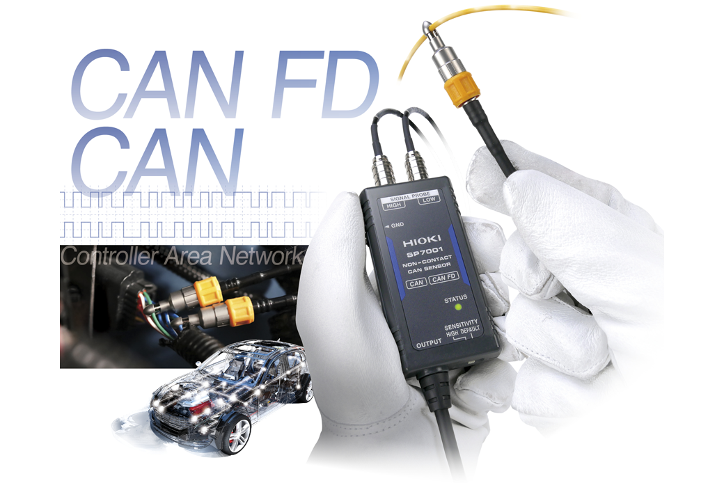
The SP7001 and SP7002 are CAN and CAN FD signal sensors that use non-contact technology to accurately capture CAN bus signals necessary for vehicle and next generation equipment evaluation and development. Improve testing productivity and efficiency by eliminating the need to peel away cable insulation or use a sub-harness that is traditionally required to obtain signals.
Vehicle CAN Bus Monitoring is Easier than Ever
The SP7001,SP7002 Non-Contact CAN Sensor allows you to acquire CAN bus signals from outside the wire coating. CAN signals are the main control signals inside a car.
Until now, engineers needed to spend immense man hours to process the CAN bus wire. With the Non-contact CAN sensor, monitoring CAN data is easier than ever. Since wires remain undamaged, the CAN bus remains unaffected even during monitoring.
Actual measurement example using NON-CONTACT CAN SENSOR
This video shows how the NON-CONTACT CAN SENSOR and MEMORY HiLOGGER LR8450-01 are used to measure the temperature of an actual vehicle. The analog data measuring the temperature inside the vehicle and the CAN data are simultaneously displayed on the waveform in real time.
Key Features
- Acquire CAN FD/CAN data immediately, simply by pinching probes over wire insulation with one-hand
- Eliminate concerns by using non-contact sensing technology
- Use in a diverse array of development and evaluation applications that demand reliability
Model No. (Order Code)
| SP7001-90 | Supports CAN FD / CAN signals, SP7001, SP7100, SP9200 set |
|---|---|
| SP7001-95 | Supports CAN FD / CAN signals, SP7001, SP9250, SP7150 set |
| SP7002-90 | Discontinued, Supports CAN signals, SP7002, SP7100, SP9200 set |
New approach means dramatically fewer man-hours
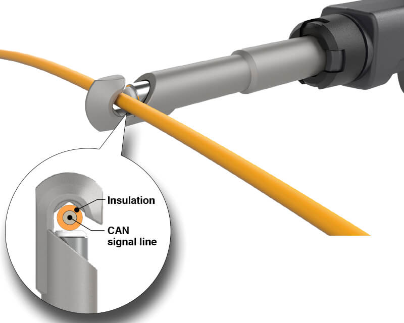
No need for a sub-harness: Simply hook probes over wire insulation
Capture CAN signals without the need to fabricate sub-harnesses or strip back cable insulation so as to significantly reduce the number of man-hours spent on test preparation.
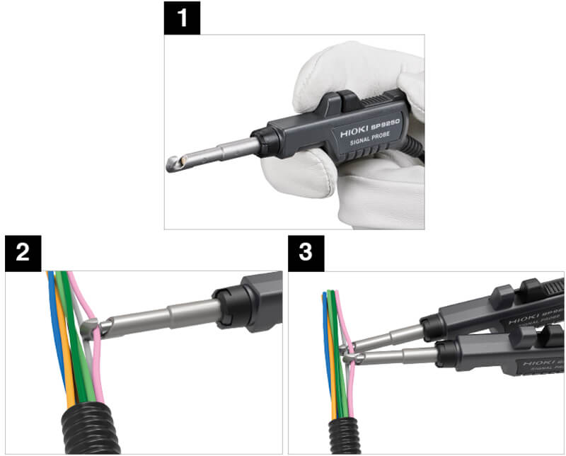
Easy setup
1. One-handed operation to open the probe tip.
2. Hook the open end to the CAN bus.
3. Automatically locks on when you release your hand.
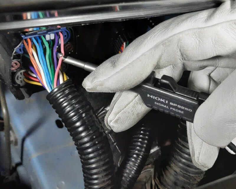
Undamaged wires for easy and safe, one-handed measurement
One-handed probing to easily reach hard-to-get-to areas that are tight, deep, and crowded with cables.
Continue using your existing CAN analysis system
Industry-standard CAN output connector pin layout. Customers who already have a CAN analysis system such as those manufactured by Vector Informatik GmbH need only connect the sensor to that system’s input terminal (via a D-sub 9-pin connector).

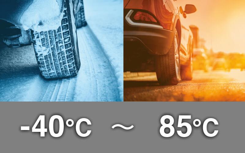
Wide -40°C to 85°C operating temperature
Acquire CAN signals in environments from -40°C to 85°C (-40°F to 185°F), the temperature range required in vehicle testing.
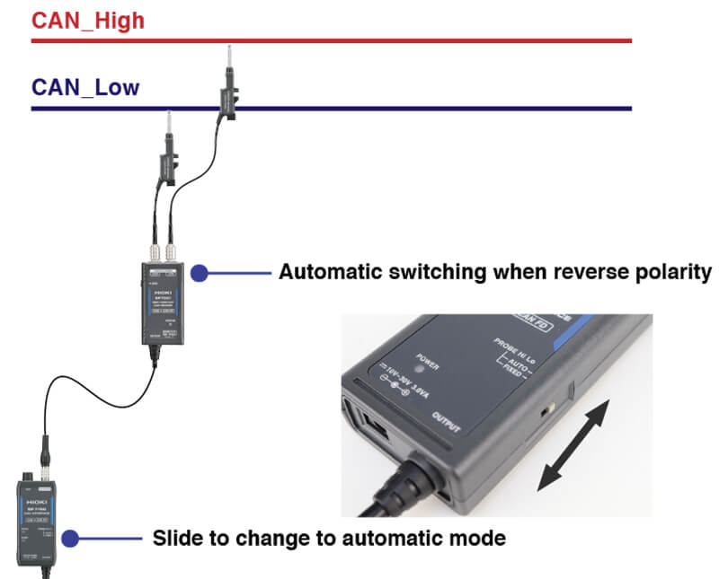
Connect probes without worrying about CAN bus polarity
If you’re using automatic input polarity mode (*), the SP7001/SP7002 will automatically switch the input polarity to ensure you can capture CAN signals properly, even if the probes are connected in reverse relative to the CAN bus’s polarity (CAN_High/CAN_Low).
*: This function will operate as long as the CAN bus load factor is at least 5%.
Adjustable sensitivity accommodates a variety of conditions
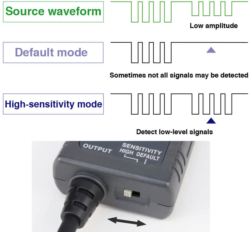
Use high-sensitivity mode (*) to broaden the detection level when the CAN signal amplitude is low relative to the CAN standard or when you are unable to detect a signal due to cable conditions.
*: It is recommended to use default mode under typical situations since it delivers the optimal level of vibration and noise immunity.
Designed not to trigger ECU security lock-outs
The SP7001/SP7002 acquires signals without changing the electrical characteristics of the CAN bus. Even if the vehicle is equipped with an ECU that has a security lock-out function designed to detect changes in the CAN bus’s electrical characteristics, you’ll be able to carry out testing without worrying about getting locked out.
Vibration resistance designed for on-road testing
The sensor delivers noise immunity designed for in-vehicle testing in a variety of road environments. Acquire CAN signals in a stable manner in evaluation testing not only on test courses, but also in vehicles undergoing test-drives on public roads.
Vibration resistance
vibration acceleration: 45 m/s^2 (4.6 G)

Noise immunity robust enough for use with EVs and HVs
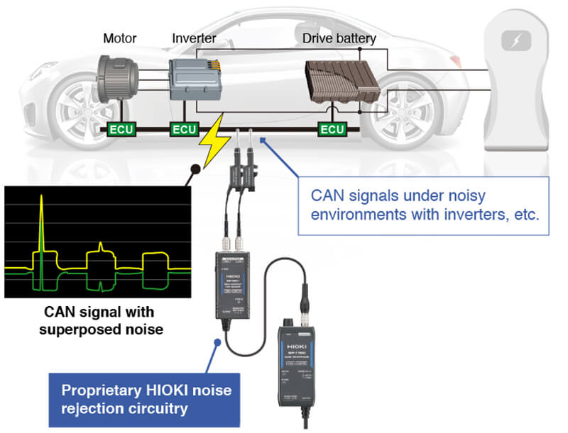
The sensor delivers enough noise immunity to acquire CAN signals in a variety of noise environments. Acquire CAN signals in a stable manner, even with vehicles such as EVs and HVs that rely increasingly on electric equipment.
Carry out testing on public roads with peace of mind since no vehicle modifications are needed
Because it acquires signals without making electrical contact, the SP7001/SP7002 is ideal for use in tests where CAN bus insulation cannot be modified. Also apply in the development of advanced driver assistance systems (ADAS) and self-driving technology.
Driving is possible while the sensor is connected to the CAN bus.
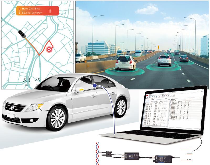
Acquire CAN signals with the same accuracy as the contact method
The non-contact method captures CAN signals reliably and accurately, just like the contact method. In addition, with a CAN signal detection delay of just 130 ns, the sensor delivers real-time performance.
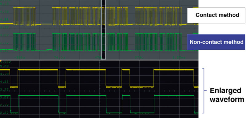
Non-contact method also excels with CAN FD high-speed signals
Unlike the contact method, the non-contact method does not distort the original signal when probing the CAN bus. This approach avoids communication errors caused by degraded communications quality.
Model with CAN FD support: SP7001
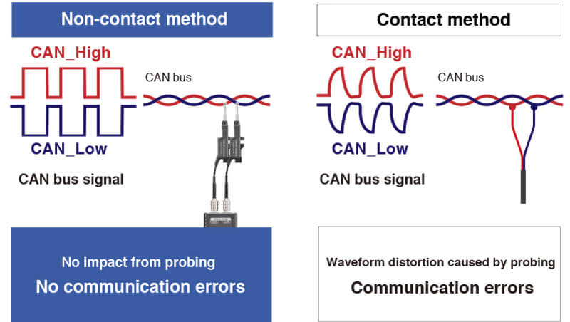
Reliably capture even infrequent events
The Non-Contact CAN Sensor does not affect the electrical characteristics of the CAN bus, allowing you to reliably catch the occasional CAN error events.
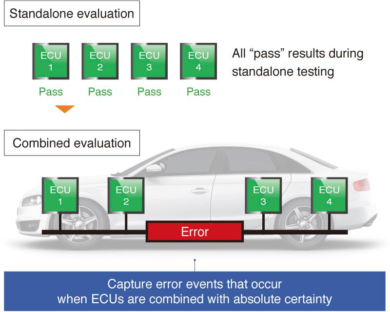
Acquire signals without needing to go through a central gateway
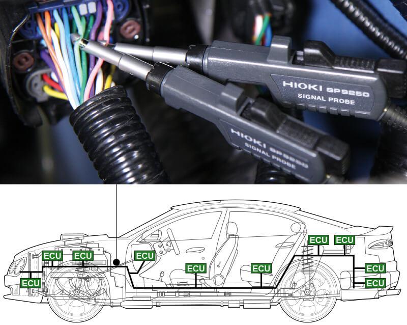
Only a tiny percentage of all CAN signals can be acquired from the OBD-II connector that is used in vehicle diagnostics. By using the product with the vehicle’s internal CAN bus, you can acquire all CAN signals.
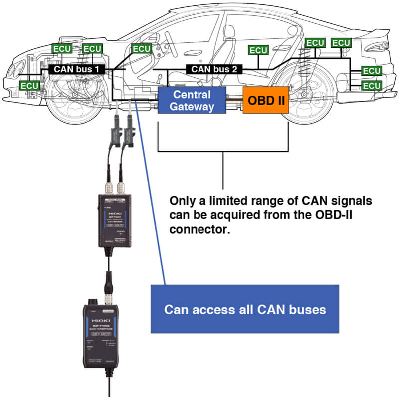
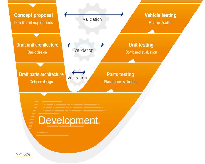
Ideal for all development processes ranging from unit to vehicle testing
1. Reduce the number of man-hours needed to prepare the vehicle for testing and then restore to original condition
The SP7001/SP7002 lets you acquire CAN data without time-consuming preparations such as fabricating sub-harnesses and modifying cables. In addition, all you’ll need to do after the test is finished is remove the sensors. There’s no impact on the vehicle.
2. Safely conduct noise application tests thanks to the isolated design
When checking the operation of vehicle sensors and ECUs, for example with tests that apply noise, the sensor protects connected devices from damage and malfunctions caused by noise because it is isolated from CAN signal lines.
3. Fostering smooth validation
The sensor makes it easy to conduct standalone and combination evaluations, including even sudden reevaluations following changes made to vehicle parts during the validation process.
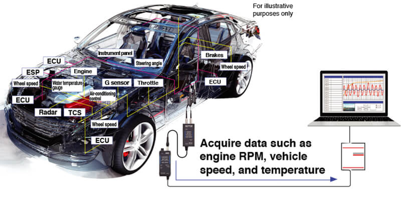
Analysis of vehicles that have more electrical equipment and data
The number of ECUs in vehicles is growing rapidly as ADAS and other safety features are enhanced and as adoption of self-driving vehicles increases, leading to more complex CAN buses. The convenience of the Non-Contact CAN Sensor makes it easy to acquire the information you need.
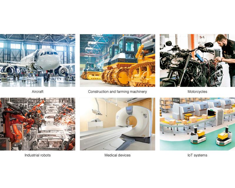
Acquire CAN signals used in a broad range of industries
It can be used not only in automobiles but also in various fields where CAN signals are used.
Product configuration
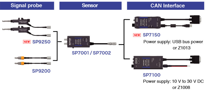
This system requires three components: the signal probe, sensor, and CAN interface.
You can either order the set models or order the system components individually. When ordering the components, please make sure to use the specific model name of each.
Basic specifications
| Detection method | Capacitive-coupled signal detection No bare-wire connections |
|---|---|
| Detectable cables | AVS/AVSS-compliant cables, External diameter: 1.2 mm (0.05 in) to 2.0 mm (0.08 in) |
| Number of channels | 1 CH (SP7150), 2 CH (SP7100) |
| Compatible communications speeds | SP7001: CAN, CAN FD 125 kbit/s to 3 Mbit/s SP7002: CAN 125 kbit/s to 1 Mbit/s |
| Total delay time | 130 ns (typical) |
| CAN terminal resistance | 60 Ω (typical), built-in |
| Signal output connector | D-sub 9-pin female |
| Operating temperature, humidity | Temperature: -40 °C to 85 °C (-40 °F to 185 °F) Humidity: -40 °C to 60 °C (-40 °F to 140 °F), 80% RH or less (with no condensation), 60 °C to 85 °C (140 °F to 185 °F), 60% RH or less (with no condensation) |
| Power supply | (1) When using the SP7001-95 or SP7150 - USB bus power (5 V DC), Maximum rated power: 1 VA - Z1013 AC Adapter: Rated supply voltage: 100 V to 240 V AC, Maximum rated power: 6 VA (including AC adapter), 1 VA (product only) (2) When using the SP7001-90, SP7002-90, or SP7100 - Z1008 AC Adapter: Rated supply voltage: 100 V to 240 V AC, Maximum rated power: 8 VA (including AC adapter), 3 VA (product only) - External power supply: Rated supply voltage: 10 V to 30 V DC, Maximum rated power: 3 VA |
| Dimensions and mass (*1) | SP7001, SP7002: 44 W × 85 H × 20 D mm (1.73 in. W × 3.35 in. H × 0.79 in. D), 180 g (6.35 oz.), Cable length: 2.5 m (8.20 ft.) SP7100: 55 W × 120 H × 25 D mm (2.17 in. W × 4.72 in. H × 0.98 in. D),130 g (4.59 oz.), Cable length: 0.3 m (0.98 ft.) SP7150: 47 W × 100 H × 20 D mm (1.85 in. W × 3.94 in. H × 0.79 in. D),100 g (3.52 oz.), Cable length: 0.3 m (0.98 ft.) SP9250:10.5 W × 24.5 H × 101 D mm (0.41 in. W × 0.96 in. H × 3.98 in. D),45 g (1.59 oz.), Cable length: 0.8 m (2.62 ft.) SP9200: φ11.6 × 33.7 H mm (φ0.46 in. × 1.33 in.), 26 g (0.92 oz.), Cable length: 0.5 m (1.64 ft.) |
| Included accessories (SP7001, SP7002) | Quick Start Manual ×1, Operating Precautions ×1 |
| Included accessories (SP7100) | Quick Start Manual ×1, Operating Precautions ×1, Spiral tube ×1, Power cable L9500 ×1, Alligator clip ×1, Ground connection cable ×1 |
| Included accessories (SP7150) | Quick Start Manual ×1, Operating Precautions ×1, Spiral tube (for fixing power cable) ×1, USB Cable L9510 ×1, Ground connection cable ×1, Alligator clip ×1 |
- *1:Dimensions do not include cables. Mass includes cables.
Sensor (2)
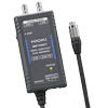
Sensor box only, supports CAN FD / CAN signals
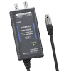
Sensor box only, supports CAN signals
Signal probe (2)
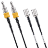
Screw type, Set of 2
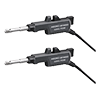
Trigger Type, Set of 2
CAN Interface (2)
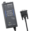
2 ch, power supply +10 V to + 30 V DC
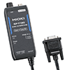
1 ch, USB power supply
Power supply (4)
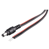
For supplying 10 V to 30 V DC
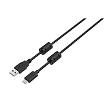
USB A-C type
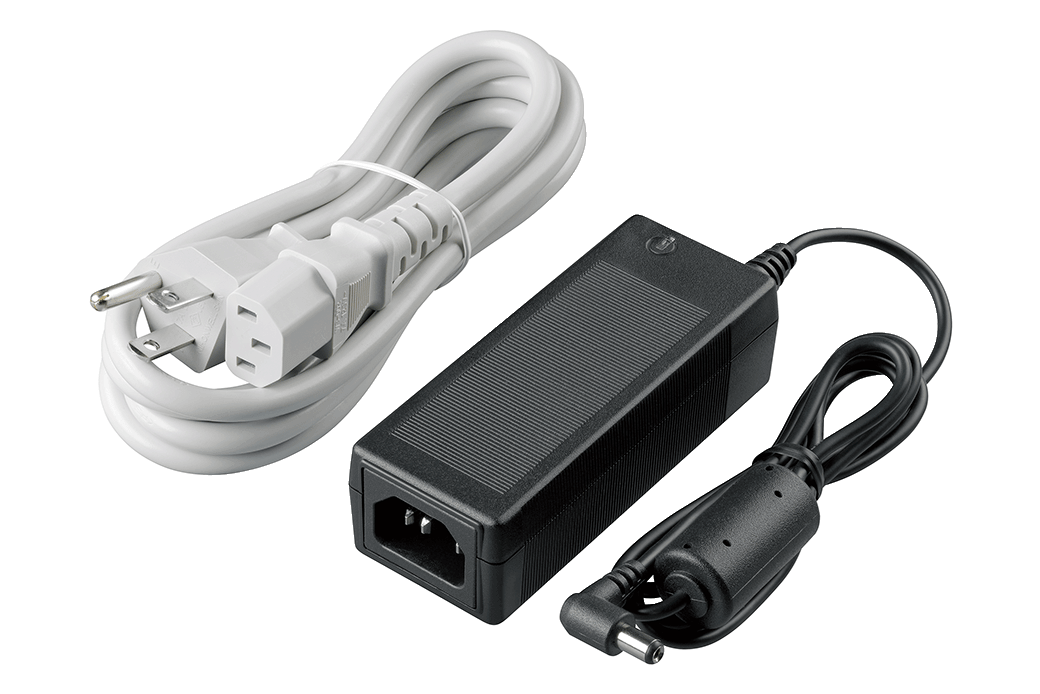
100 V to 240 V AC
100 V to 240 V AC
Cable (1)
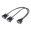
For CH1, CH2 output branch
Case (1)
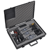
Hard case, 2CH can be stored

