How to Test a Transformer
How are transformers tested? Explore testing methods and measurement tips!
Overview
Transformers are an extremely important type of electrical equipment. When one malfunctions, it could lead to significant damage for the company that was using it. To prevent that eventuality, it's necessary to perform evaluation measurements during development and robust testing during manufacturing, and to carry out maintenance in the form of regular testing and inspections.
This page introduces standard transformer evaluation measurement and testing methods that are in common use.
What is a transformer?
Transformers are used to change an AC voltage, for example by stepping it up or stepping it down. They also play an insulating role. In this latter role, they protect the users of electric equipment by isolating the input and output sides of the power supply circuit so that electricity on the input side cannot flow directly to the output side.
Examples that are familiar to most people include the small transformers that people use during overseas travel and the bucket-shaped transformers that you can see mounted on utility poles.
Transformers convert electricity to an easy-to-use voltage based on the necessary load at the facility in question, from high voltage to low voltage. You may be wondering, “Why not just transmit electricity at an easy-to-use voltage in the first place?”
However, transmitting electricity via power lines at low voltages causes substantial transmission losses. Power plants use high voltages to reduce current while transmitting electricity in order to limit transmission losses.
Basic transformer evaluation testing
Below are some examples of some of the basic parameters used to evaluate transformers:
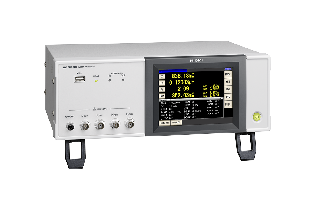
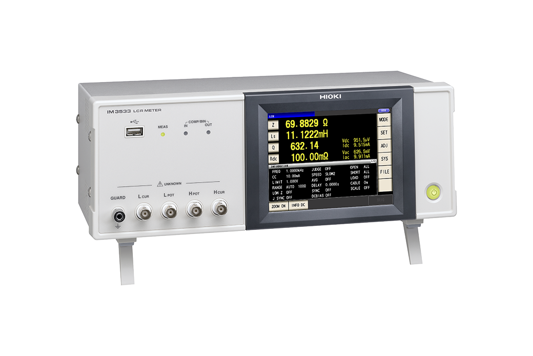
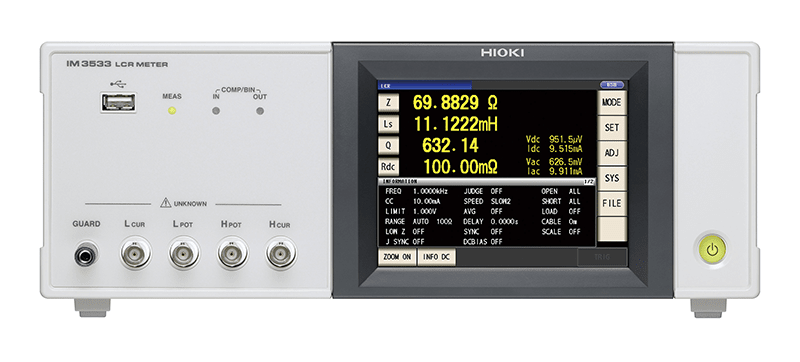 Product used: LCR Meter
Measuring primary inductance (L1) and secondary inductance (L2)
The instrument is connected to the primary and secondary sides of the transformer and used to measure primary and secondary inductance. All other windings are left in the open state during these measurements.
Measuring leakage inductance
In an ideal transformer, shorting the output also shorts the input, but in actuality, leakage inductance remains even when the output is shorted. Leakage inductance can be obtained by shorting the secondary side and then measuring the primary-side inductance.
Winding capacitance
This test measures the winding wire capacitance between the primary and secondary sides of the transformer. This quantity can be measured by connecting the instrument to each winding, one at a time.
Measuring mutual inductance
Mutual inductance can be calculated as (M = (La - Lo) / 4) by measuring inductance with the same phases connected in series and with opposite phases connected in series.
Measuring the turn ratio
An approximate turn ratio can be calculated by connecting a resistance R to the secondary side and measuring the inductance Z on the primary side. The calculation is (N = √[R/Z]).
Transformer temperature-rise testing
Temperature-rise testing is used to determine whether a transformer’s temperature rises behind the specifications value when operating under rated conditions. In such testing, the temperature of components such as the transformer’s oil or winding is measured. The following three measurement methods are used:
Actual load method
This type of temperature-rise test is carried out while the transformer operates under the rated load. It’s not realistic to use this method when testing high-capacity transformers. Consequently, it is used to test low-capacity transformers.
Loading-back method
In this method, measurements are made while supplying the no-load-loss and load-loss supply capacities individually. Since the supply capacities used in the test are low, the method can also be used to test high-capacity transformers such as those used to supply electric power. Precautions must be taken since the method requires at least two transformers with the same rating, and measurement results need to be temperature-corrected.
Equivalent load method
In this method, the temperature rise is measured after shorting one of the transformer’s windings, applying a current to the other winding from a power supply of the rated frequency, and applying the loss equal to the sum of the no-load loss and the load loss. Note that since the total loss is supplied as the load loss, it's necessary to know the underlying figure in advance. Additionally, like the loading-back method, this method requires temperature correction and other procedures.
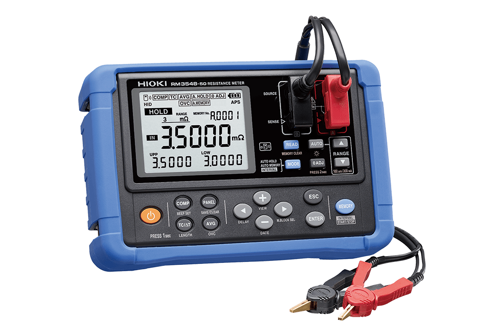
Temperature-rise testing can also be performed using resistance measurement. The temperature rise can be calculated from the measured resistance value and ambient temperature.
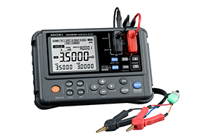 Resistance Meters
(with temperature conversion function)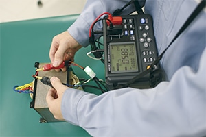
Other transformer tests
There are a wide range of transformer tests in addition to the methods described above. In addition to withstand testing and insulation resistance testing, which are used for other devices as well, transformers are subjected to testing to assess their resistance to earthquakes, weather, heat, cold, and humidity. Techniques such as no-load-loss testing, which serves as an indicator of energy savings for devices such as transformers and motors, are also used.
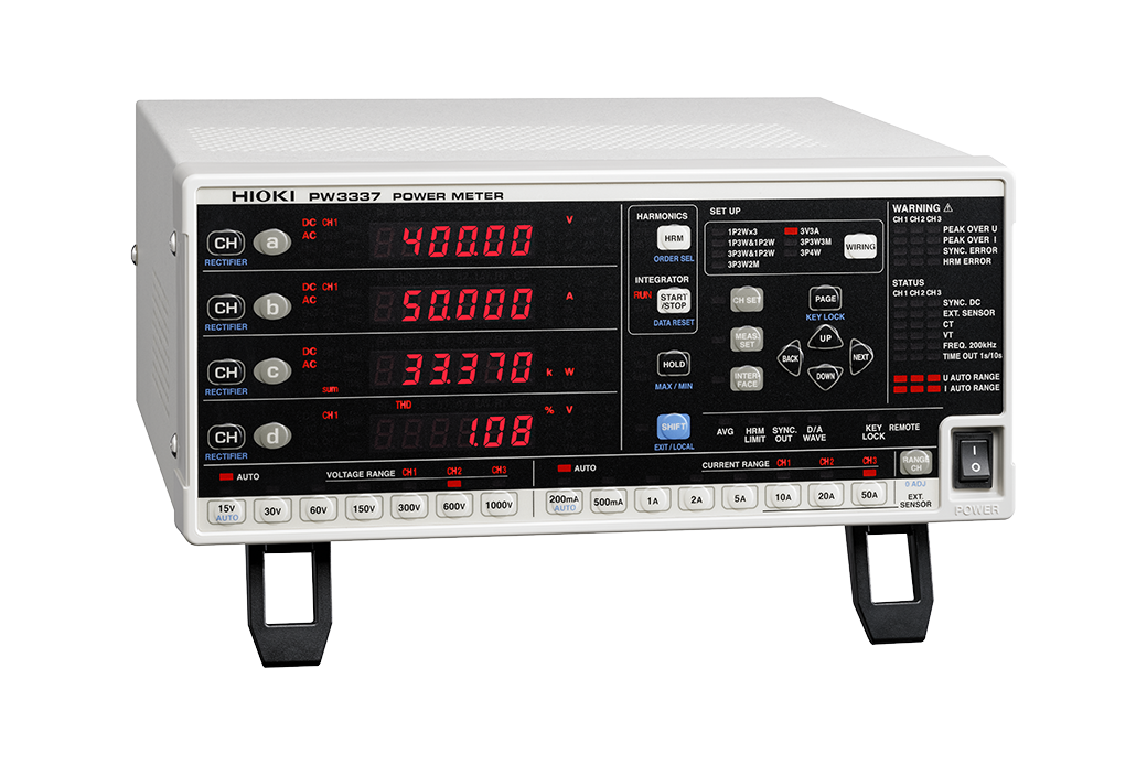
Hioki’s Power Meter PW3337 and PW3336 can measure active power with a high degree of accuracy at low power factors thanks to a power factor effect of 0.1% or less at low power factors.
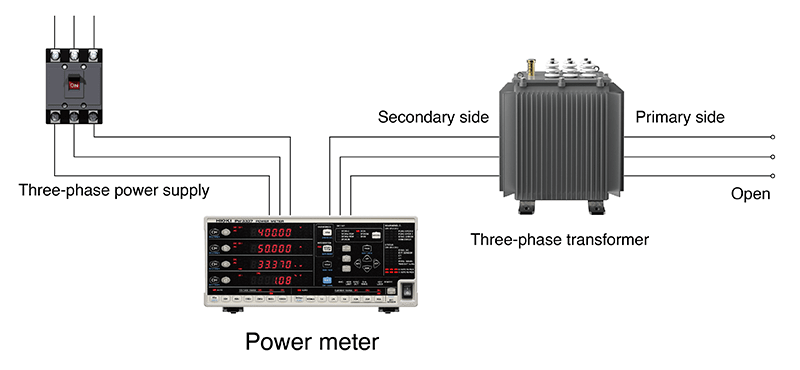 No-load Loss Measurements for Transformers
Summary
Transformers convert high-voltage electricity from power plants to the voltages necessary for use in apartments, buildings, manufacturing plant equipment, and electrical equipment. There are numerous methods for testing transformers. This article has introduced some basic tests. If you need to test a transformer, please refer to the testing methods introduced here.