IMPEDANCE ANALYZER IM3570
V3.14 May 08, 2024
- If you are unable to download software, please check the following:
- Please register a my HIOKI account and then use it to log in to the my HIOKI service.
- Product firmware (product upgrades) and computer application software can only be downloaded for products you have registered on the my HIOKI service.
| Firmware (IM3570_V314.zip) | |
|---|---|
| Procedure on how to update the firmware (IM3570vupE_02.pdf) |
Version upgrade should be conducted by a qualified technician familiar with the functions and operations of model IM3570.
If you are uncertain as to how to proceed, please contact your local Hioki distributor for assistance.
・All software provided here is freeware and the best version currently available.
・If the problems or errors during this download and install lead to malfunction, please contact your dealer or Hioki representative.
・The ownership, intellectual right and all other associated rights relating to the software provided here belong to Hioki E.E. Corporation.
If you have read and understand the information above and wish to proceed then please download the designated files.
As for version upgrade procedure, please download ”Procedure on how to update the firmware” which describes the preparation and procedure for upgrading firmware after downloading the files.
Precaution when updating firmware:
・To conduct the version upgrade, USB memory stick is required.
・During the version upgrade process, don’t turn off the power to the IM3570 or don’t remove the USB memory stick from the slot. Turning power off will result in failure to upgrade the IM3570, and the instrument must be returned to the Hioki factory for repair.
Firmware for the model IM3570
The latest firmware version is shown below. A version update is highly recommended if you are running older version.
・Firmware Version : V3.14
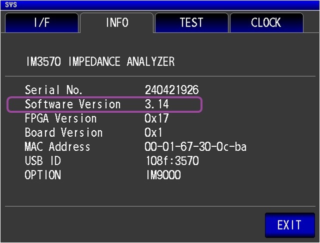
How to check the version number
The version number of firmware can be checked by selecting the ”INFO” tab of the System screen.
Version Upgrade History
V3.14 (April 2024) Newest Version
Fixed bugs:
1. Fixed a bug where if measurement frequency is changed to over 1 MHz, the measured signal level would be set to the upper limit even if it was less than the upper limit (CV level 1 V, CC level 10 mA).
2. Fixed a bug where the current measurement signal level would be changed by the following communication command that changes the measurement signal level in current measurement signal mode.
:LEVel:CVOLTage, :LEVel:VOLTage, :DCResistance:LEVel:VOLTage, :DCResistance:LEVel:CVOLTage
Improvement:
1. Improved to allow open and short corrections to be performed with the DC bias function ON, when the optional DC bias voltage unit 9268-10 or DC bias current unit 9269-10 is connected.
V3.13 (December 2021)
Fixed bugs:
1.Fixed the problem that the Model E of equivalent circuit analysis, when the frequency type of electromechanical coupling coefficient is fr-fa and the phase is not zero-crossed, the analysis does not work properly.
2. Modified the small bug.
Improvement:
1.Changed so that when the response data is larger than the send buffer size, the MAV bit is set to 1 when the buffer is full.
V3.12 (April 2020)
Improved Functions:
1. Changed the way units of measurement and parameters are displayed when files are saved in the USB memory stick: [Ω]->[ohm], [θ]->[PHASE], [°]->[deg]
2. Added support for the use of the control characters LF as a command terminator.
V3.11 (January 2017)
Fixed bugs:
・In continuous mode, sending one of the following commands immediately after the instrument acknowledged the EOM signal caused an execution error.
:MEASure?, :MEMory?, :MEASure:CONTinuous:COMParator?
・During USB communications with a computer running Window 8, Window 8.1, or Windows 10, the instrument sent back two responses.
V3.10 (April 2016)
Fixed bug:
While setting to Internal trigger and measuring continuously, send a query command continuously by GP-IB I/F, measuring rarely stops.
V3.09 (August 2015)
Fixed bug:
If the measurement range switched between 300 Ω range or less and 1 kΩ range or more during measurement with both of the following setting configured, a measurement error (error in an averaged value display) was increased.
・The measurement range was set to AUTO.
・The number of averaging times was set to 002 or more.
Improvement:
Always the optimum measurement ranges are selected during the open circuit or short circuit compensation measurement even in a noisy environment.
V3.08 (July 2015)
Fixed bugs:
1. If the sweep frequency is set to 1 MHz or more in analyzer mode, invalid measurement signal levels were able to be configured.
2. If the communication command “*TRG;:MEASure?” was sent during using the continuous measurement function, the instrument’s attempt to execute the command caused no correct values to be replied, resulting in an execution error.
3. If the measurement condition with low Z high accuracy mode was defined as a measurement target for continuous measurement by using the continuous measurement function and started measurement, a voltage of 6V or lower was output from the Hpot terminals.
4. With a trigger mode setting for continuous measurement that was set to STEP, judgment results of the equivalent circuit analysis function were not output on completion of every single measurement.
5. If the on/off settings for items that of continuous measurement had not been performed were switched during the measurement with a trigger mode for continuous measurement that was set to STEP, no triggers became accepted.
Improved Functions:
1. The automatic changing range behavior of the LCR and analyzer functions with the average function enabled is improved, resulting in the other improvement such that the most appropriate measurement range is settled even if the ranges are changed several times.
2. The automatic changing range behavior during the open circuit and short circuit compensations is improved, resulting in the other improvement such that the error of “Adjustment Failure” is not likely to be issued.
V3.07 (January 2015)
1. Fixed the drawing outside the display range which occurred when the sweep range and sweep point are set at the same point.
2. Fixed the bug that when saving data as a text file (CSV file) to a USB flash drive, which instrument might get hung up.
3. Fixed the unreflected interface setting which occurred when loading settings from USB flash drive.
4. Fixed the measurement value to positive value which occurred when DC resistance measurement is performed by OPEN correction value by high resister or SHORT correction value by low resister.
V3.06 (August 2013)
1.The measurement value may go ”OVER” under a certain condition that the frequency is set to more than 1MHz, after a measurement which performed with measurement signal level CV or CC, and the frequency less than 1MHz.
V3.05 (August 2013)
1.Fixed a bug that sometimes the instrument get hung up when using the LAN interface.
2.Fixed a bug that the instrument can’t accept the connection when the instrument is disconnected during communication of LAN.
V3.03 (September 2012)
Added Functions:
1.Added a communication command (:HCOPy:DATA?) which acquires BMP data from the measurement screen.
2.Added a function that saves/reads (ALL LOAD) all function settings including the panel into the USB flash drive.
3.Added a function that interrupts measurement when there is a contact check error during Continuous Measurement.
4.Added a function that pauses the measurement when the judgement is FAIL during Continuous Measurement.
5.Added a ”step function” which requests triggers in each panel during Continuous Measurement.
6.Added a function that calculates the electromechanical coupling coefficient. (IM9000 option)
7.Added a function which performs equivalent circuit analysis after reading the measurement value saved in the USB flash drive. (IM9000 option)
Improved Functions:
1.Faster speed of the instrument’s overall performance/operation.
2.Faster measurement speed during Continuous Measurement.
3.Improved the internal trigger averaging method when there is a measurement anomaly.
4.Changed the parameter that performs average, from ”Z-PHASE” to ”G-B(R-X)”.
5.Restored both the ”comparator function” and ”BIN function” settings in LCR mode when switching from Continuous Measurement Mode to LCR Mode.
6.The equivalent circuit mode (Serial/Parallel) is displayed as the parameter in the ”panel save” and ”panel load confirmation” screens.
7.Improved the icon that shows the access status of the USB flash drive.
8.When performing SPOT compensation, the compensation values that was acquired before will be initialized.
9.When sending the command (:FILE:FOLDer) which specifies the folder in which to save the files, the saving mode has changed from ”AUTO” to ”MANUAL”.
10.When changing the ”measurement parameter” during analyzer measurement, the measurement value reverts to the value that was present when the power was turned on.
11.When changing the measurement conditions during Step Measurement, the instrument is reverted to the initial measurement condition and does not perform the next measurement.
12.The settings of trigger synchronous output can be changed when in Analyzer Mode.
13.Disabled equivalent circuit analysis and simulation during measurement. (IM9000 option)
14.When the peak value cannot be found during equivalent circuit analysis upon querying the peak frequency using the command (:MEASure:ANALysis:PEAK?), rather than returning with an operation error, the actual error value (99999E+28) will be returned. (IM9000 option)
Fixed bugs: the following issues were remedied
1.During DC measurement and the CC function or the Current Limit Function was enabled, sometimes the generated signal level was not output according to the set level.
2.When both the CV(CC) and Limit Functions were enabled and an error occurred, it was difficult to identify whether the error was a CV(CC) or a Limit Error.
3.When measuring using ”comparator” or ”BIN measurement” with an internal trigger, it was found that after compensation but before returning to the measurement screen, measurement would nevertheless occur once.
4.When touching the screen while measurements were being saved to the USB flash drive, sometimes the instrument hung.
5.Upon sending the command to set the LOAD compensation capture conditions during DC measurement (:CORRection:LOAD:DCResistance:CONDition), the level value setting was accepted in terms of mA units.
6.When printing the screen during measurement with an internal trigger, sometimes the part showing the measurement values was illegible.
7.In LCR mode whereby the second and third parameters were set to the same value, after the scaling compensating coefficient for each was set, upon measuring in Analyzer Mode, the scaling for the third parameter was found to be uncompensated.
8.In the Memory Function, when the query (:MEMory?) to acquire the memory data was sent despite the absence of any memory data, sometimes data failed to be saved in memory thereafter.
9.The command (:MEMory:POINts) to set the memory size was valid even when the Memory Function was turned ON or IN.
10.Problems with the header section of the header of query (:COMParator:SLIMit:MODE?) that acquires the judgement mode of the third parameter of the comparator function.
11.A screen error sometimes occurred when changing the measurement conditions using PC communications during Analyzer Mode.
12.A drawing error sometimes occurred when executing the command to change the sweep conditions during Analyzer Measurement.
13.The instrument hung when the command ”*TRG;:[compensation start command]” was executed during Analyzer Measurement.
14.The instrument hung when executing the [compensation start command] during Step Measurement in Analyzer Mode.
15.When sending the query (:MEASure:CURSor?) to acquire the measurement value of the cursor after sweep measuring from high frequency to low frequency, the correct value was not returned.
16.An output error from the EXT I/O’s /ERR terminal occurred during Analyzer Measurement.
17.When sending the search command (:SEARCH), the B cursor followed the same search conditions as the A cursor to conduct the search.
18.In making the settings for ”Start-Stop” and ”Center-Span” in Analyzer Measurement, the minimum step for frequency could not be set.
19.An output error from the EXT I/O’s /ERR terminal occurred during Continuous Measurement.
20.The instrument sometimes hung when the STOP key was pressed on the screen during Continuous Measurement.
21.When sending a query (:MEASure:CONTinuous:COMParator?) in binary mode to acquire the overall judgement results during Continuous Measurement, the returned response was in ASCII format.
22.When sweep measuring from high frequency to low frequency and then limiting the analytical range of the equivalent circuit, analysis could not be performed. (IM9000 option)
23.The cursor did not display properly when the No.1 parameter was turned OFF in the X-Y graph display. (IM9000 option)
V3.02 (September 2011)
Fixed bugs:
1.Fixed a bug that the instrument might get hung up depending on certain setting conditions when using the instrument in combination with ”Segment sweep” and ”Peak comparator” functions.
2.Fixed a bug that ”Cursor search” may not function properly, depending on how you set up segment sweep and frequency.
3.Fixed a bug that a saved DC voltage limit value was one tenth of actual value when saving data to a USB flash drive in a text format.
4.Fixed a bug that when querying Load compensation reference value(:CORRection:LOAD:REFerence?), if ”Rs-X” was set as its response message format, X value was not be returned.
5.Fixed a bug that when setting display commands for analyzer mode (:SWEep:DISPlay), it could not be changed to X-Y display (except when using IM9000 option).
V3.01 (August 2011)
Added functions
1.Added Communication commands to acquire the Open/Short/Load compensation data.
2.Added a function to control frequency range when performing Open and Short compensation.
3.Added an EOM output method (EXT I/O) that can maintain a low (ON) state for a preset time before reverting a signal to high (OFF) after completing measurement.
4.Added an ”Auto search” function when ”Continuous measurement” function is set to ON.
5.Added Communication commands to allow ”Panel save/load” via a USB flash drive.
6.Added a function that can simultaneously save both text (CSV) and BMP files to a USB flash drive.
7.Added a function to save monochrome BMP to a USB flash drive.
8.Added communication commands to return the number of the target panel for ”Continuous measurement”.
Improved functions:
1.A trigger input is disabled from sampling start to end of measurement. Now added a function that disables a trigger input from the last trigger input to end of measurement.
2.When saving BMP file to a USB flash drive, the set date and time of the instrument is now saved together.
3.Units will not be printed in case of measurement errors, such as ”OVERFLOW”.
4.Printer communication speed is now changeable.
Factory default preset has been changed: 19200bps→9600bps
Fixed bugs:
1.Fixed a bug that when saving data as a text file (CSV file) or a BMP file to a USB flash drive, the instrument might get hung up.
2.Fixed a bug that while saving data as a text file (CSV file) or a BMP file to a USB flash drive, if you switch a screen display in order to check contents of files, the instrument might get hung up.
3.Fixed a bug that when saving measurement conditions to a USB flash drive with the Panel save function, parameters of load compensation conditions on No.2 to No.5 could not be saved.
(Even in the above case, when the data, which had been saved with the Panel save function, was loaded, the measured value would not be affected because compensation coefficient was normally loaded.)
4.Fixed a bug that when saving measurement conditions to a USB flash drive with the Panel save function, Search target parameters selected for B cursor for the purpose of checking the measured values of Analyzer mode could not be saved.
5.Fixed a bug that when Comparator or BIN function was enabled, if you tried to save the measured values in text form to a USB flash drive, the setting information of No.2 and No.4 parameters were also saved.
V2.04 (July 2011)
Fixed bugs:
1.Fixed a but that error information of the last measurement remained.
2.Fixed a bug that terminator of response message could not be set via a communication command.
3.Fixed a bug that when the GPIB command LLO (Local Lock-Out) was active, even if the GPIB command GTL (Go To Local) was sent, a local operation could not be restored.
4.When performing AC measurement in Low Z high accuracy mode, setting Constant Current level and using DC bias, if the total value for the measurement signal level (AC level + DC bias value) becomes [V] due to changing DC bias, AC level will be compulsorily changed in order that the total value becomes [V] . Fixed a bug that the AC level value was compulsorily changed to one tenth of the desired one.
5.Fixed a bug that when performing continuous measurement, Comparator (BIN) judgement result was not reflected on overall judgement result.
V2.02 (April 2011)
Improved functions:
1.Faster touch panel response.
2.Cancel function is now available on Panel calibration screen.
3.When a key on a touch panel screen is pressed, the key pressed is now recognizable by its highlighting and with a green circle on it.
V2.00 (January 2011)
Fixed bugs:
1.Fixed a bug that when performing Analyzer measurement, if your desired measurement time interval was 85 seconds or longer, it could not be set.
2.Fixed a bug that when performing ”AC+DC measurement”, if measurement error occurred for AC measurement only, the output from ERR terminal of EXT I/O reverted to high (OFF) level immediately before finishing measurement.
3.Fixed a bug that when any measurement was not performed after the power was turned on or after a change of DC measurement conditions, if load compensation values were obtained in the order of AC value and DC value, the load compensation values became abnormal.
Added functions:
1.Added a ”Detection level monitoring function”: to detect an error, such as abnormal contact or noise by monitoring level fluctuation.
2.Added a function to update a screen display of ”Continuous measurement” result after finishing measurement. (The measurement time will be shorter than the one when the screen is updated every time measurement is performed.)
3.Added a query command to acquire a measured value in ”Continuous measurement” mode.
4.Added an ”Auto Search” function for Analyzer mode (: after finishing measurement, measurement value search is automatically started.)
5.Added a function to set search functions individually for each cursor A and B.
Improved functions:
1.Changed measurement status description in a response message for a query of measurement results (: MEASure? or : MEMory?).
2.Improved various screen displays.