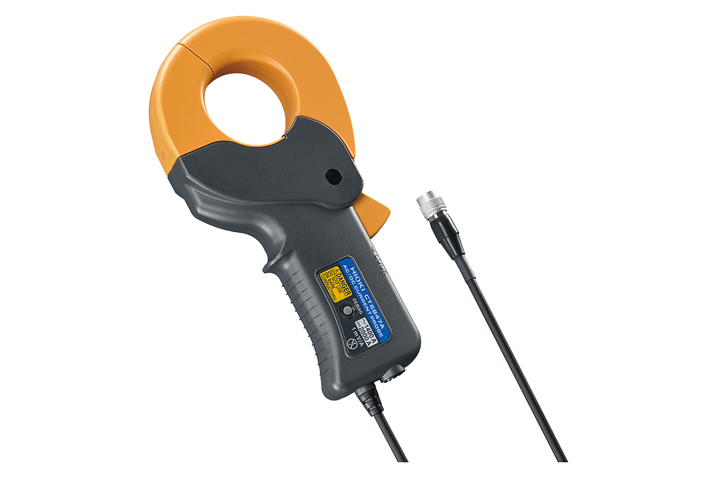
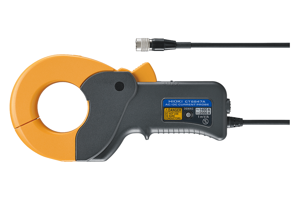
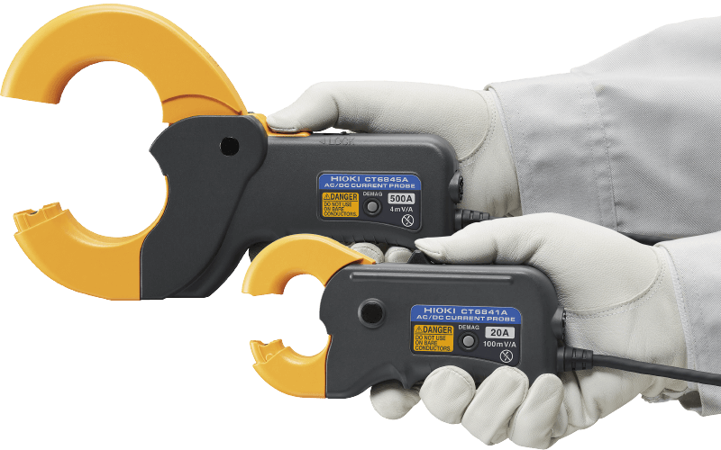
AC/DC CURRENT PROBE CT6847A
Accurate Current Measurement with Flexible Clamp-on Design
NEW
-

-
 Insulated conductor
Hioki precision current clamps enable accurate, non-intrusive AC and DC current measurement without interrupting the circuit.
Precision current clamps are used where accuracy, ease of use, and minimal impact on the test setup are essential, including vehicle on-board measurements (incl. WLTP), power electronics testing, efficiency analysis, and measurements in hard-to-access environments.
Key Features
- Frequency bandwidth DC to 70 kHz, Rated current 2000 A DC, 1400 A AC
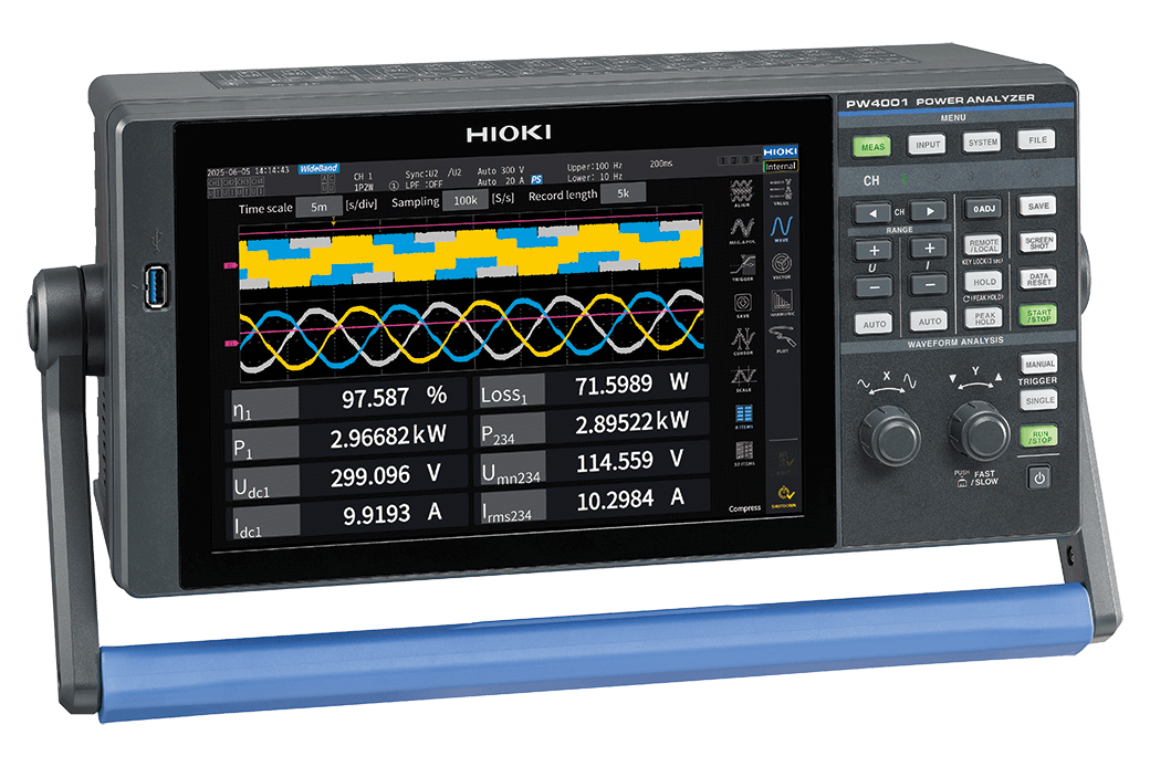
- Guaranteed combined accuracy when used with Hioki power analyzers
- Plug-and-play with Hioki Power Analyzer and Memory HiCorders
- Ideal for use in environmental testing with broad -40°C to 85°C temperature range
- Ideal for EV inverter evaluation and PV power generation PCS evaluation
- Single-handed operation and robust locking mechanism
Model No. (Order Code)
| CT6847A |
|---|
Clamp-type sensors that eliminates the need to cut lines
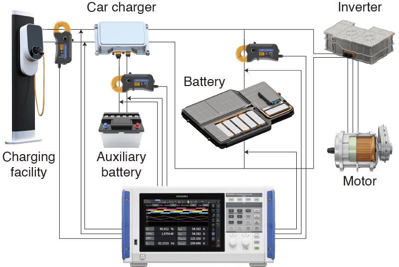
Clamp-style current sensors can be affixed without cutting the line under measurement. Thanks to that design, they can measure current in applications where it’s not possible to cut lines, including testing of EVs on chassis dynamometers and evaluation of operational solar power systems.

Range reliability testing that complies with the WLTP international standard
The CT6840A series can measure current in operating vehicles since there’s no need to cut cables. Combined with a power analyzer, these instruments can accurately integrate current and power during charging and discharging of system batteries in order to make WLTP-compliant vehicle energy consumption measurement.
Realizing unparalleled measurement precision in a clamp-style design
While clamp-style current sensors are generally praised for their convenience, they usually pose disadvantages in terms of measurement precision. However, the CT6840A series delivers unparalleled measurement precision in a clamp-style design, allowing accurate measurement of DC power in battery-powered EVs and solar power systems.
Accurate current measurement across a broad operating temperature range of -40°C to 85°C
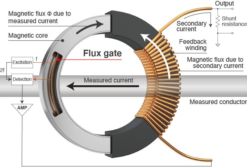
Temperature characteristics are an issue for current sensors that can manage DC current. The CT6840A series uses the flux gate detection method. Unlike the standard Hall element detection method, the flux gate method is more resistant to temperature variations, allowing instruments to accurately measure current in a variety of test environments.
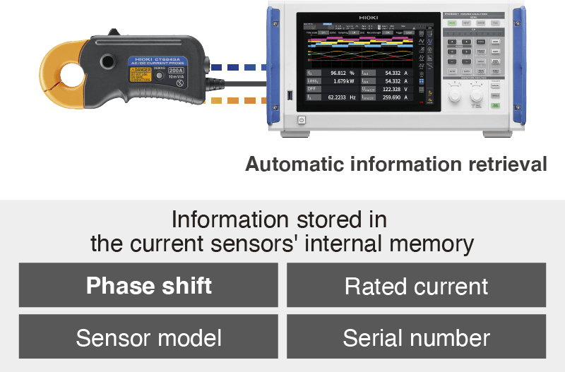
Get reliable power results with the right setup—automatically
When paired with compatible power analyzers, phase-shift errors in the current sensor are automatically corrected.
Because HIOKI designs and manufactures both power analyzers and current sensors in-house, correction can be applied based on factory inspection data. This minimizes errors caused by sensor-to-sensor variation, even in dynamic measurements with high-frequency components, and improves confidence in power evaluation results.
It also helps engineers quickly achieve the correct setup, even without specialized knowledge of phase correction.
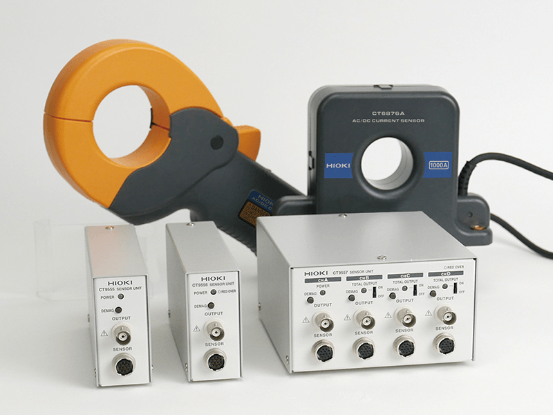
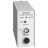
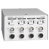
External Power Units (Compatible with Various Measurement Instruments)
These external power units supply power to current sensors and enable connection to a wide range of measurement instruments, including power analyzers, recorders, and oscilloscopes*.
Single-channel and four-channel models are available to support different measurement setups.
*Connect to instruments with an input impedance of 1 MΩ or higher.
Basic specifications
| Rated current | 2000 A DC, 1400 A AC | |||||
|---|---|---|---|---|---|---|
| Frequency bandwidth | DC to 70 kHz | |||||
| Diameter of measurable conductors | Max. φ 50 mm (1.97 in.) | |||||
| Max. allowable input | ±2400 A peak (Within 1 cycle at 40°C (104°F) or less, for waveforms with a period of 10 ms or more) |
|||||
| Output voltage | 1 mV/A | |||||
| Output resistance | 50 Ω ± 10 Ω | |||||
| Accuracy (amplitude) ±(% of reading + % of full scale) |
DC 0.15% + 0.01% DC < f ≦ 16 Hz 0.2% + 0.01% 16 Hz < f ≦ 100 Hz 0.15% + 0.01% |
|||||
| Linearity | ±20 ppm Typical | |||||
| Common-Mode Voltage Rejection Ratio (CMRR) |
DC to 1 kHz:130 dB or greater 1 kHz to 10 kHz:120 dB or greater 10 kHz to 50 kHz:100 dB or greater (effect on output voltage and common mode voltage) |
|||||
| Automatic phase correction | Automatically performs phase correction when connected to a compatible Hioki power analyzer. | |||||
| Operating temperature and humidity range | -40°C to 85°C (-40°F to 185°F), 80% RH or less | |||||
| Standards | Safety IEC 61010 EMC IEC61326 |
|||||
| Withstand voltage | AC 4,260 V | |||||
| Power supply | Power supplied from compatible Hioki power analyzers, sensor units, or current units. | |||||
| Max. rated power | 7 VA or less (When measuring 1000 A/55 Hz with ±12 V power supply) | |||||
| Dimensions and mass | Approx. 238 mm W × 116 mm H × 35 mm D (approx. 9.37 in. W × 4.57 in. H × 1.38 in. D), 1040 g |
|||||
| Cable length | Approx. 3 m (9.84 ft.) | |||||
| Included accessories | Markup bands(×6), Carrying case, Instruction manual | |||||
Maximum Number of Connectable Sensors
| Host Instruments | Max. Number of Connections |
|---|---|
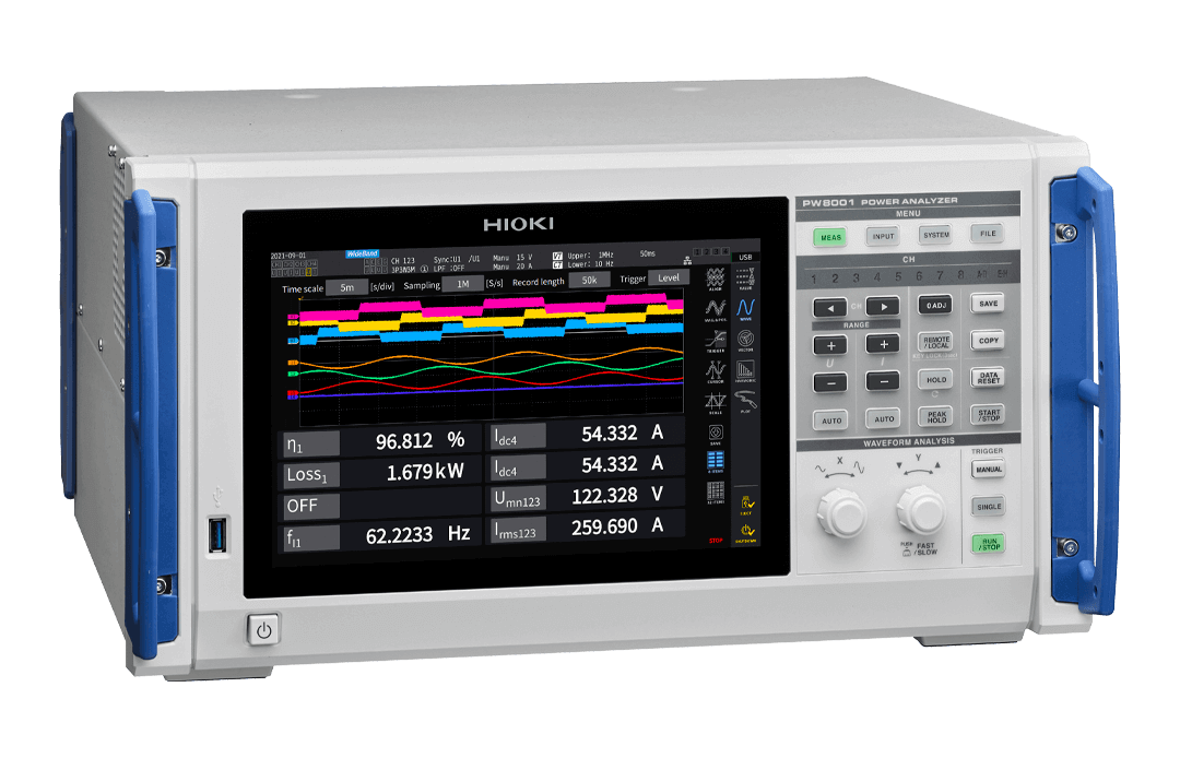
| Power Analyzer PW8001 | 7 Units |
| Power Analyzer PW4001 | 4 Units |
| Power Analyzer PW6001 (Discontinued) | 5 Units |
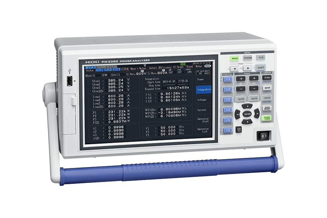
| Power Analyzer PW3390 (Discontinued) | 3 Units |
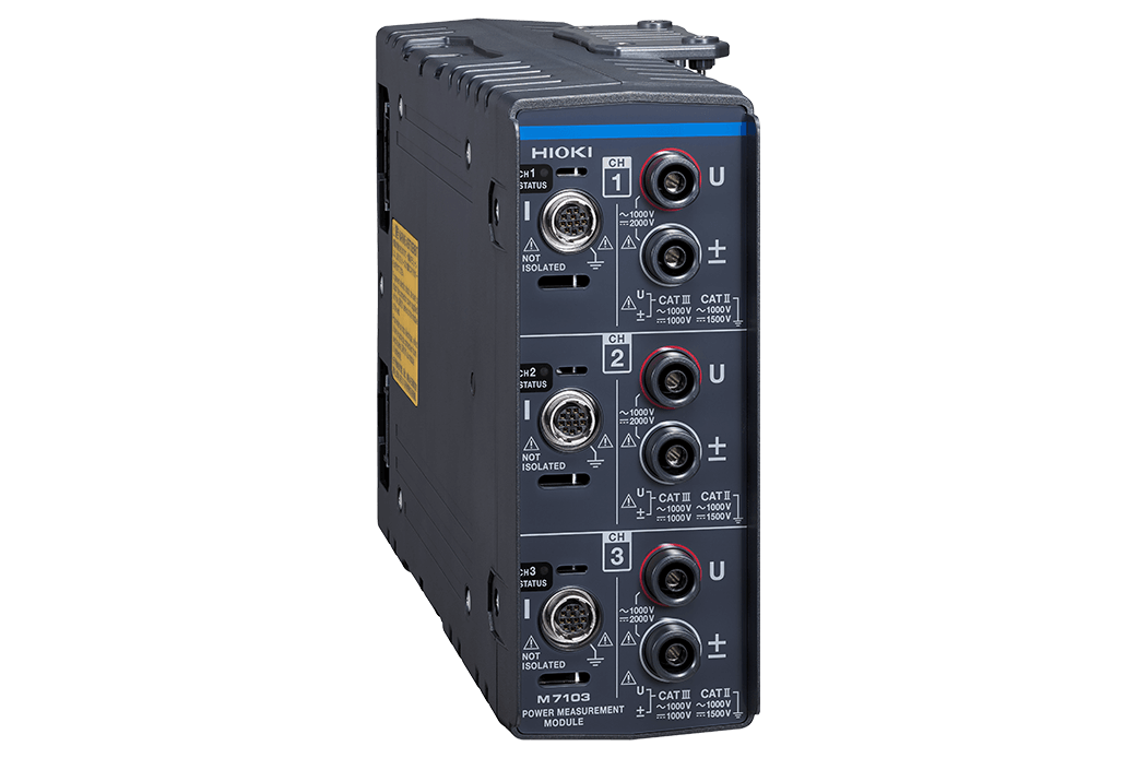
| Power Measurement Module M7103 | 2 Units |
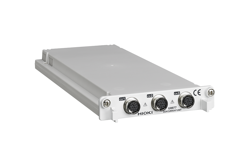
| Current Unit U8977 | 2 Units |
| Sensor Unit CT9555 | 1 Unit |
| Sensor Unit CT9556 | 1 Unit |
| Sensor Unit CT9557 | 4 Units |
External power supply, connection cord (5)

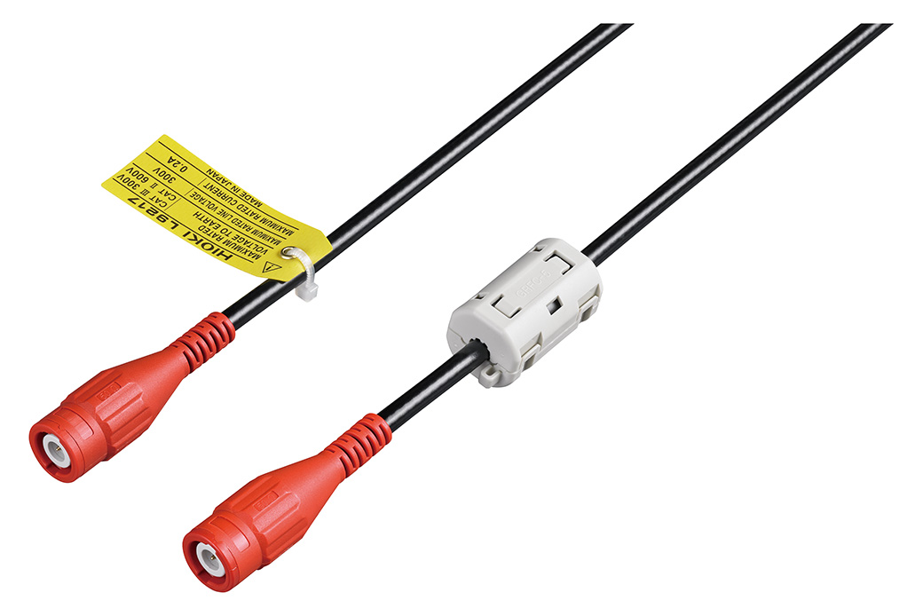
Cord has insulated BNC connectors at both ends, 1.6 m (5.25 ft) length
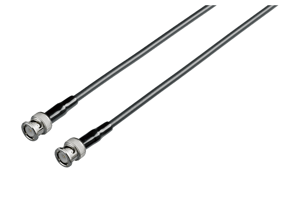
Cord has metallic BNC connectors at both ends, use at metallic terminal, 1.5 m (4.92 ft) length
Extension cable (1)
The CT9902 connects up to 2 cables in series (Accuracy addition required)
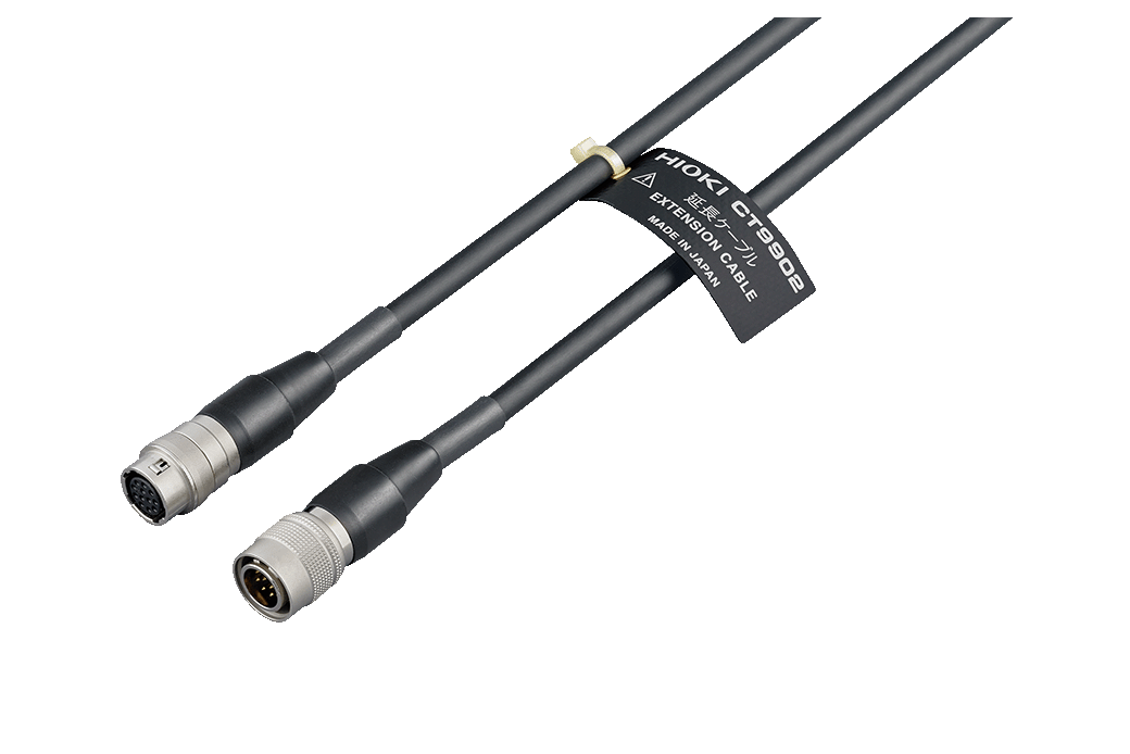
5 m (16.41 ft) length, ME15W (12 pin) - ME15W (12 pin) connector
-
AC/DC CURRENT PROBE CT6841A, CT6843A, CT6844A, CT6845A, CT6846A, CT6847A
 Instruction Manual
Japanese
Instruction Manual
Japanese
English
Simplified Chinese Ver.00
-
AC/DC CURRENT PROBE CT6847A
Ver.00