Phase detector principle and method of use
Phase detector principle
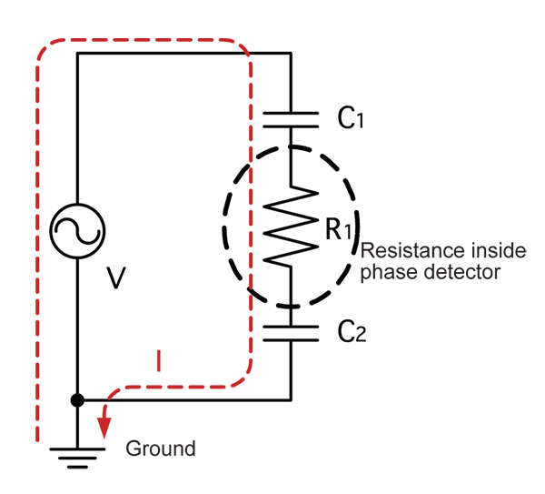
No-metal-contact phase detectors usually detect voltage by means of electrostatic induction. When an electric circuit (live wire), the phase detector’s voltage clip, the phase detector, the user of the instrument, and the ground make contact, electrostatic coupling of the five form a closed circuit, and an extremely small amount of current flows. This minuscule current appears as a voltage drop at a high resistance inside the phase detector, allowing acquisition of a waveform corresponding to the voltage relative to ground. The PD3129 Phase Detector utilizes this voltage detection principle to acquire a voltage waveform for each of three phases and detect the phase order.
Procedure for using a phase detector (how to use the Phase Detector PD3129)
1. Checking operation prior to use
Clip the voltage clips to a single wire (live wire) carrying at least 70 V AC and verify that the line voltage indicator lights up.
• If the indicator lights up: The instrument is functioning properly.
• If the indicator does not light up: The instrument may be malfunctioning.
2. Checking a wire to see if it’s live
Use either of the voltage clips to check a wire to see if it’s live.
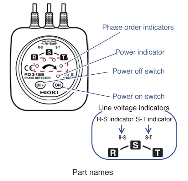
Voltage clip used Line voltage indicator
R (red) R-S indicator only
S (white) R-S indicator and S-T indicator
T (green) S-T indicator only
3. Detecting phase
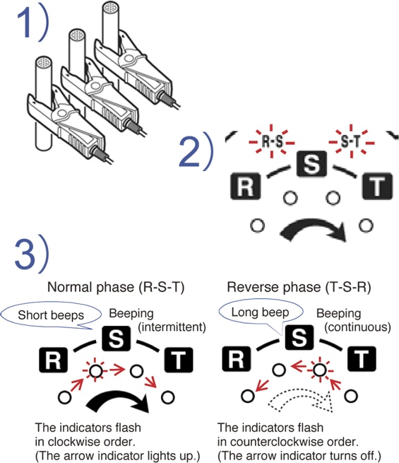
1) Attach the phase detector’s voltage clips to a 3-phase AC circuit’s wires outside the insulation.
2) If all wires are live, the R-S and S-T line voltage indicators will light up.
3) If the phase order indicators flash in the order indicated by the arrow, the the connection phase order is correct (R-S-T). The instrument will beep intermittently.
How to use the Phase Detector PD3129/PD3129-10
Introducing safe, contactless phase detection! This video introduces the Phase Detector PD3129/PD3129-10, which provides visual and aural notification of detection results.