Trip Testing of High-voltage Circuit Breakers in Power Transformer Installations
Introduction
Circuit breakers play an extremely important role in modern society. They protect everything from homes to hospitals from dangerous electric phenomena like lightning and harmful high-frequency noise. These breakers go through stringent tests right after being manufactured as well as during scheduled maintenance. However, each circuit breaker varies based on use, and each person overseeing these tests require slightly different things. These variations require test technicians to be flexible in order to test and produce satisfactory test reports.
This article will first give an overview of circuit-breaker trip-tests (for those who need it) and will then present arguments as to why Hioki’s Memory HiCorder MR8847A is a great—if not the best—tool for the job because of flexibility in data processing and probing.

1. Overview of trip tests
So, what is the trip test?
For readers less familiar with the “trip test,” this section will explain it.
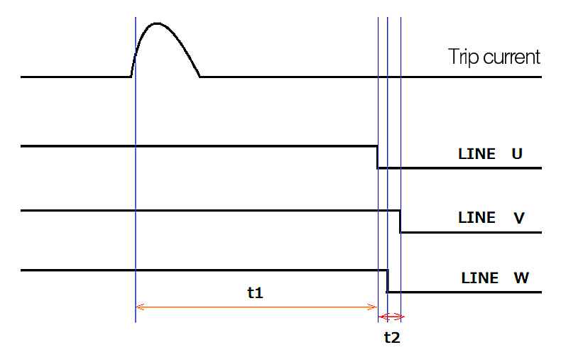
The “trip test” is in essence making sure that the spring mechanism of the breaker switch performs fast enough after receiving the signal to cut off or let in power from the grid. The pass/fail judgement is based on the recorded timing of the control signal that triggers the breaker switch and the recorded timing of the mechanical open/close operation. A minute time-delay inevitably occurs due to the mechanical nature of the spring mechanism. This time-delay is compared against a minimum tripping time for a pass/fail judgement. In the case of 3-phase power systems, there is an additional comparison done between the timing of each spring-loaded switch. The timing variation of the three switches are compared against a minimum variation time. Through regular maintenance in these ways, technicians can ensure that circuit breakers switch properly.
Types of measurement required in trip testing
The following are steps of the trip test.
1. The circuit-breaker’s connection to the primary side (power mains) and secondary side (power line that goes to the facility and/or devices) are disconnected for safety. Also, the breaker should be grounded.
2. The test instrument is set up and test measurement started
At this stage, all of the necessary probes need to be connected. After confirming that all connections have been made, the start button of the instrument can be pushed.
3. The test trip-button on the breaker is pushed
The breaker has a separate power source that sends out a control signal for tripping the breaker. By pushing a button on the breaker, the breaker is tripped. Since the measuring instrument was turned on in step 2, its sensors will acquire both the control signal and the logic signal showing that the physical switching operation occurred.
4. Disconnect the test instrument
5. Reconnect the breaker to the primary and secondary side
The test is over so you can now reconnect and return power to the facility.
6. Evaluate and process the data for the test report

So, what is the trip test?
For readers less familiar with the “trip test,” this section will explain it.
The “trip test” is in essence making sure that the spring mechanism of the breaker switch performs fast enough after receiving the signal to cut off or let in power from the grid. The pass/fail judgement is based on the recorded timing of the control signal that triggers the breaker switch and the recorded timing of the mechanical open/close operation. A minute time-delay inevitably occurs due to the mechanical nature of the spring mechanism. This time-delay is compared against a minimum tripping time for a pass/fail judgement. In the case of 3-phase power systems, there is an additional comparison done between the timing of each spring-loaded switch. The timing variation of the three switches are compared against a minimum variation time. Through regular maintenance in these ways, technicians can ensure that circuit breakers switch properly.
Flexibility in data processing
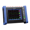
The Memory HiCorder (short for Hioki-recorder) MR8847A’s flexibility in data processing makes it especially useful for trip-testing.
Usually, field instruments are designed for just a few purposes and lack much flexibility in their ability to process data. However, in the case of the MR8847A, even though it is made for field work, it also contains the high specs usually associated with advanced R&D use. This makes it flexible to respond to a wide array of report demands.
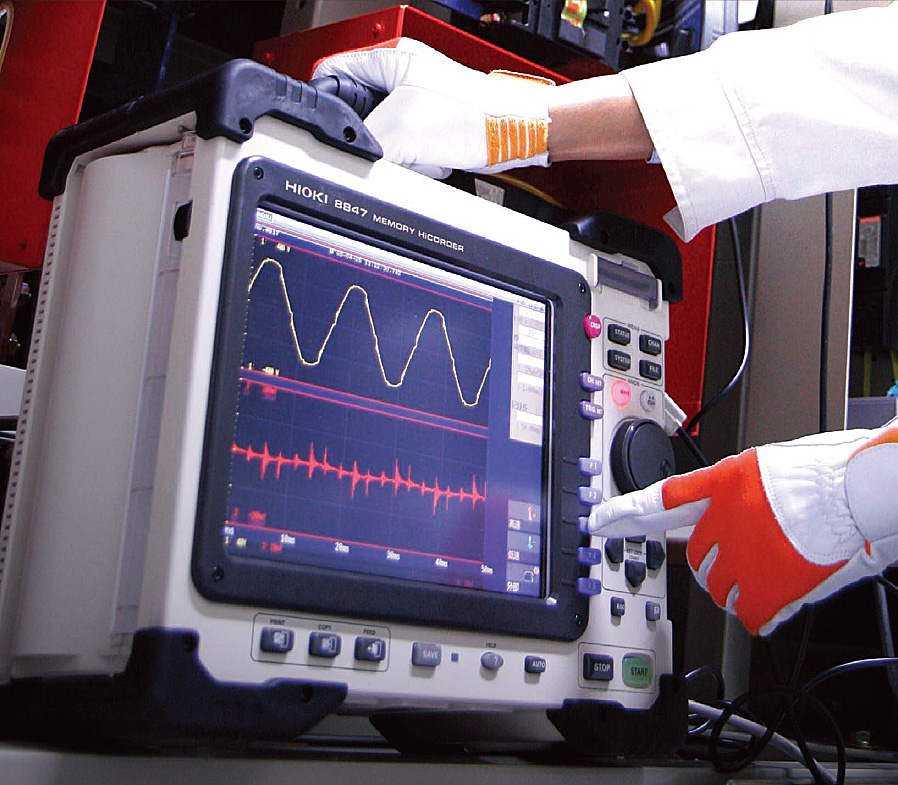
As a field measuring instrument, this HiCorder is field-ready with features like general durability and rubber padded handle and edges. Its larger buttons are perfect for operators wearing protective gloves (unlike touch-screens common in R&D instruments). The large screen is popular among technicians who want to check details in the field.
In terms of data processing, the MR8847A provides great flexibility to meet the various demands for trip-test reporting. As the reader is most likely aware, the test criteria used in trip tests depend on the circuit breaker. Some breakers fall under IEC standards, while others do not. This means that the test instrument must be flexible in its ability to adapt to various test criteria of that specific trip-test. In addition, each person to whom the technician reports (e.g., facility manager) may demand their own specific report format, requiring flexibility in data processing abilities.
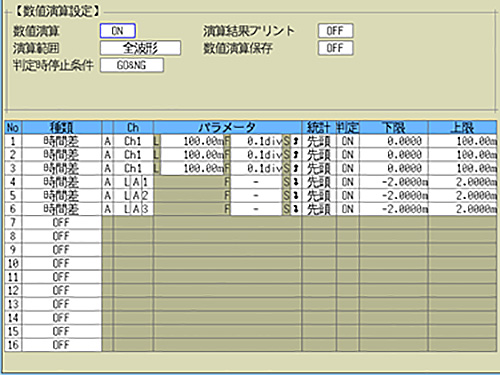
The MR8847A excels in data processing for report creation
This HiCorder makes the standard trip testing easy with its Time Difference Calculation function, but it also has many functions and features that enable flexibility in data analysis and data reporting. Having similar functions to its sister model the MR6000 (Hioki’s flagship R&D HiCorder), the MR8847A has many preinstalled numerical calculation and waveform calculation functions as well as various analysis and display modes. If the facility manager asks for analysis from different perspectives or presentation of the data in different ways, the technician can rely on the HiCorder for support. The calculated/analyzed data can then be uploaded as a CSV for easy report creation. As a side note, the MR8847A comes equipped with a printer that enables technicians to print in the field so that they can explain to the manager on pen and paper. In these ways, even though the Memory HiCorder MR8847A is well-suited for field work, its flexible data processing and multimedia features make it perfect for the ever-changing test criteria and reporting demands of trip testing.
2. Hioki instruments recommended for use in circuit breaker trip testing
Flexibility in probing
Another point in which this Memory HiCorder provides much-needed flexibility is in probing and wiring.
The trip test involves sensing control signals and the mechanical open/close motion of the breaker switch. However, it is not uncommon to be asked to test breakers only to find that the usual tester’s probes are physically unable to access the measurement point (too large to clamp, too cramped to probe, etc.) or that the current/voltage rating does not match the signal being measured.
Hioki’s wide line-up of sensors and probes can provide the flexibility needed for varying probing demands. Hioki is widely accredited for its high-precision current sensors. But in reality, it provides the market with a wide range of current and voltage probes, from affordable to state-of-the-art. Whether it be small spaces, large wires/busbars, or minute control signal currents, the technician can rest assured in knowing that Hioki’s lineup can provide the probe right for the job.
In addition, Hioki also provides flexible solutions to in-field problems. One such solution is eliminating the need for cluttering power cables of current sensors (for control signal sensing). Current sensors which require a power source, usually have a separate wire for power. Hioki’s sensors use the same cable for power and current sensing, eliminating this source of clutter. Another practical solution is eliminating the need for an external power source for logic signals (for the switch-motion sensing). Typically, an external voltage power source is used to apply a logic voltage, which is then sensed by the test instrument’s voltage probe. Hioki’s logic probes both apply and sense the voltage, thereby eliminating the need for a separate voltage source. The current ensors’ and logic probes’ power sources are just a few examples of probing solutions to in-field problems from which the technician can choose.
In these ways, Hioki’s large lineup of current sensors and probes provides flexibility to adapt to the special demands of the site, making
the Memory HiCorder MR8847A an even more attractive unit for trip testing.
Principal equipment used
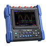
Waveform recorder MEMORY HiCORDER MR8847A
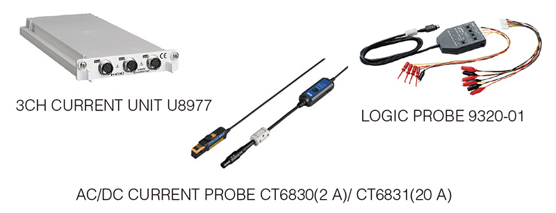
Input unit 3CH CURRENT UNIT U8977 × 1 slot
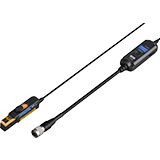
Current Sensor AC/DC CURRENT PROBE CT6830 ×1
Logic sensor LOGIC PROBE 9320-01 × 1
*This Application Note describes an example setup recommended for use in trip-testing circuit breakers. The specific equipment recommended for any given application varies with the purpose of measurement.
Current sensors have different rated currents and should be chosen based on the purpose of measurement and the location being measured.
Conclusion
The Memory HiCorder MR8847A’s data calculation, analysis, and media capabilities give it the flexibility needed to meet the pass/fail criteria and reporting demands original to each trip test. Furthermore, there are many probes and sensors that can be paired with it, providing flexibility in both plain specs as well as in-field convenience. In these ways, Hioki’s Memory HiCorder MR8847A provides the technician with the versatility and capabilities demanded by the various requirements of trip tests for circuit breakers.
As of late, there have been global trends toward increased electrification of drive-systems for transportation and data-centers used for digitization and artificial intelligence. These and other trends increase the global demand for electricity—and consequently the need for breakers that protect electrical systems. This means that more and more breakers will need to be trip-tested.
We at Hioki are determined to provide society with the tools and solutions required to make changes for a better, safer, and more sustainable society. This application of trip testing using the Memory HiCorder MR8847A is just one example of this determination. We look forward to working with on-site technicians for the realization of such a society.
For comprehensive details on the Memory HiCorder MR8847A, please visit the product page. For inquiries such as quotes, demonstrations, and trial usage, please use Hioki’s contact form for a personalized reply from your closest or most appropriate Hioki representative. We are here to help tailor solutions to your needs.
Current probe and current unit
The trip signal that operates a circuit breaker in the event of an abnormal grid condition takes the form of a DC current. Consequently,
a current probe capable of detecting current in the DC band is required in order to measure the trip current. Please choose a probe model with a rated current that’s suitable for the magnitude of the current being measured.
Recommended probe: AC/DC Current Probe CT6830 (2A) or CT6831 (20 A)
In general, DC current probes require wiring both to supply power to drive the probe and to output data. The 3ch Current Unit U8977 uses dedicated connectors to simplify wiring, allowing it to supply power, output a data signal, and acquire information such as the current probe’s rating.
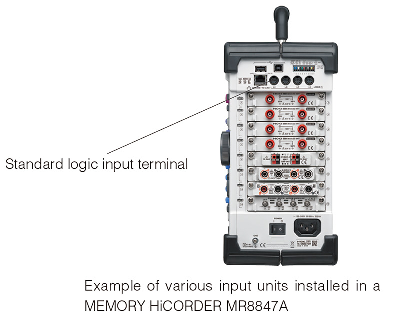
Logic probe
Although it’s typical to apply a DC voltage from an external source in order to acquire the contact signal, an optional logic probe can be used to acquire the contact signal directly. In addition, logic probe output can be connected directly to the Memory HiCorder MR8847A since the instrument ships standard with 16 channels of logic input. No optional logic unit is needed in order to measure up to 16 logic channels.
3. Related products
PS: other options… (‘cause we just can’t help ourselves)
Here are a few other options that you may be interested in if you’re involved in trip testing.
Don’t need the flexibility?
If you always test the same breaker or need a less high-end instrument, you may want to try the Memory HiCorders MR8870, MR8875, or MR8880. The flexibility in data analysis and high-end probes may not be as advanced as the MR8875A, but they may be a better fit for a more limited application.
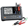
Need to measure contact resistance of the breaker?
Hioki’s portable Resistance Meter RM3548 is recommended for use in applications that involve measuring primary-circuit contact resistance as part of the maintenance of circuit breakers at substations.
Requests for demonstration units and questions about applications should be directed to Hioki’s customer service hotline.