Winding the Secondary Coil (Detection Winding) when Measuring Iron Loss with the 2-Coil Method
Measure Iron Loss with the 2-Coil Method with High Precision
High-frequency reactors are used in a variety of locations in electric vehicles (EVs) and hybrid electric vehicles (HEVs), including step-up DC/DC converters between the battery and the inverter and AC/DC converters in battery charging circuits. To boost overall system efficiency, developers need to improve the efficiency in each constituent circuit, and reactors are one component that is responsible for a large amount of loss in these circuits, making accurate measurement of reactor loss a critical part of improving overall system efficiency. In general, because most of these reactors are switched on and off at high frequencies, it is widely recognized that directly measuring reactor loss is extremely difficult.
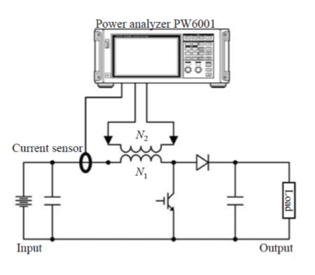
In preparing for measurement, one important but often overlooked element is how the reactor's detection coil is wound. This application note provides guidance on how to specifically wind a detection coil. Learning the methods is extremely valuable for carrying out precise measurement of reactor loss in booster chopper circuits as shown in Fig. 1.
Fig. 1. Reactor loss measurement with 2-coil method
Key Points in Winding
The key to winding is to improve the coupling coefficient between the primary coil (N1 (turns)) and the detection coil (N2 (turns)). Detecting all the magnetic flux generated from the primary coil with the detection coil makes it possible to measure the reactor loss without error generated by the leakage flux.
The wire diameter of detection coil may be made smaller as no current will be flowing through it.
The wire diameter of detection coil may be made smaller as no current will be flowing through it.
Important Points to Consider
The voltage induced across the detection coil depends on the turn ratio. Ensure a sufficient number of winding turns so that enough voltage is induced when measuring it with a Power Analyzer, but bearing in mind that in order to keep the effects of the input impedance of the power analyzer small, the number of turns of the detection coil should not be too high. You can get the best results with N1 = N2 in many cases.
Toroidal Cores
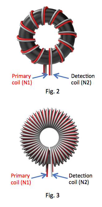
By winding the primary coil along with the detection coil as illustrated in Fig. 2, the coupling coefficient between primary and detection coils can be maximized.
Practically, the primary coil would be already wound on a core. In that case, wind uniformly the detection coil on the primary coil as shown in Fig. 3.
Fig. 2. How to wind primary and detection coils
Fig. 3. How to wind detection coil on primary coil
Fig. 3. How to wind detection coil on primary coil
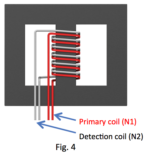
EI-shaped Cores
Basically for EI-shaped cores, the same applies as for the toroidal core. By winding the primary coil along with the detection coil as illustrated in Fig. 4, the coupling coefficient between primary and detection coils will be maximized. When the primary is already wound on a core under test, wrap the detection coil evenly over the primary coil.
Fig. 4. How to wind detection coil on primary coil