Using the Earth Tester FT6031: Simple measurement and the 2-pole method
Performing zero-adjustment
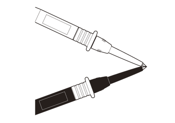
Connect the black L9787 Test Lead to the E terminal on the instrument and the red L9787 Test Lead to the H (C) terminal and connect (short) the tips of the test leads.
Then operate the ground resistance tester to perform zero-adjustment.
Connecting the measurement cords
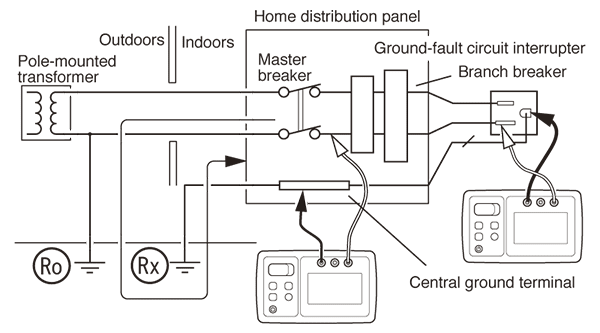
The figure provides an example of how to connect the measurement cords when measuring a commercial power supply whose neutral (N) side is grounded.
A Class A grounding installation or buried metal object such as a metal pipe can be used as a low-resistance ground resistor for measurement purposes. Be sure the low-resistance ground resistor is at least 5 m away from the grounding electrode being measured. Accurate measurement will not be possible if the resistor is located too close to the grounding electrode.
Measuring the ground resistance
Using a voltage detector or other suitable instrument, verify that the neutral (N) side of the commercial power supply is not carrying a voltage.
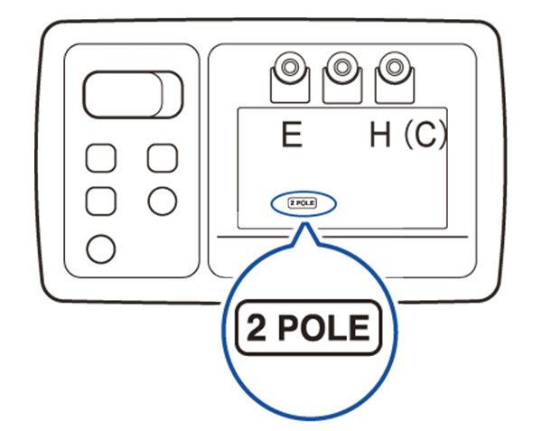
Press the power button to turn on the instrument. Then press the Fn button to display “2 POLE.”
Connect the black L9787 Test Lead to the grounding electrode that is serving as the measurement target, and connect the red L9787 Test Lead to the neutral (N) side of the commercial power supply.
The instrument will display the ground potential.
Pressing the MEASURE button will cause the instrument to automatically perform the sequence of measurements described below. The measured value will be displayed for about 3 seconds, and the HOLD indicator will light up.
The instrument will check whether the ground potential peak value falls within the allowable range. Then it will measure the ground resistance. The instrument will measure the total of the grounding electrode’s ground resistance and the ground resistance of the neutral side of the commercial power supply (Rx + Ro).