Versatile Instrument for Various UPS Operational Tests
As a result of global warming and other types of climate change in recent years, power outages and momentary interruptions caused by lightning strikes are occurring more frequently. Such anomalies are a huge problem for facilities like factories and data-centers because their precision equipment can be damaged or destroyed by these
power anomalies and power outages. This makes the installation of uninterruptible power supplies (UPS) a crucial part of risk management for these facilities.
The job of a UPS is to provide a stable supply of power in the event of issues with the grid. To ensure that such systems can perform that job when called upon, it’s necessary to verify reliable operation in an efficient manner by simulating a variety of power anomalies before they occur in operation situations.
This application note aims to describe issues of UPS testing and provide solutions to these issues that are unique to Hioki.
Issue
There are many types of UPSs, and many of their differences are based on the various kinds of power that are required by the facilities and equipment which they protect. For example, some facilities require single-phase power, while others require 3-phase. Consequently, a measuring instrument used to test these systems must be able to measure each phase. In this way, various power requirements create a demand for the large variety of UPSs currently on the market. This variety in UPSs, as well as the multitude of power anomaly types, makes it difficult to test UPSs’ operation. The following list outlines just some of the challenges in UPS testing taken on by Hioki’s Memory HiCorder series (Hioki’s line of high-end multi-phenomena measurement and recording devices).
Issues taken on by Hioki Memory HiCorders
·Safety:
Unlike typical loggers and oscilloscopes to which Hioki Memory HiCorders are often compared, HiCorders hold a unique distinction from them by having fully isolated channels. This means that separate circuits (such as that of the primary and secondary side of a UPS) which are meant to have different grounds/neutral-lines, can be safely measured. Since each channel has its own ground (is isolated), short-circuiting can be averted, and proper measurement of voltage can be ensured. This not only makes the HiCorder suited for measuring voltage of different circuits, but also makes this device the clear choice for ensuring the safety of the operator from electric shock (as well as protecting the instruments involved from malfunction).
·Reliability:
The combination of Hioki’s Memory HiCorder’s high-speed sampling and long storage time, and sensors’ accuracy enable reliable measurement.
Hioki has led the current sensing industry for many years in accuracy, precision, and practical design. Since Hioki’s current sensors are designed and manufactured in-house, it is able to have extremely strict and top-of-the-market control over their sensors’ precise frequency response characteristics. This then enables Hioki’s advanced measuring instruments like the HiCorder to compensate for high-frequency inaccuracy that traditionally haunts CT sensors.
In addition to this, the high-speed sampling and long-term data storage, make HiCorders far superior to other typical instruments used for UPS testing. Although typical power quality analyzers (PQA) are often the go-to for typical power quality testing they lack the sampling speed to capture extremely fast or fine anomalies. Furthermore, since typical PQAs’ are not designed for long-term recording of data, they often fail to capture momentary anomalies that are by nature unpredictable. These two points are solved with the Memory HiCorder as their sampling speed and data storage capacity are a few of its many versatile strong points.
As such, the high sampling speed, long recording time, and high current-sensing accuracy characterized by the combined use of Hioki’s Memory HiCorder and precision current sensors make them the most reliable instrument duo for UPS testing.
·Efficiency:
By adding the Arbitrary Waveform Generator Unit, you can efficiently perform simulations and measurements by simulating complex power anomalies without using a function generator. (See in more detail below in “Using a HiCorder to simulate power anomalies and test UPS operation.”)
Below are a general explanation of the requirements presented in UPS testing and a few of practical examples of how Hioki’s Memory HiCorder can be used to safely and efficiently evaluate UPSs.
1. How does UPS operation testing work ?
UPS operation testing is designed to confirm that, in the event of power loss or voltage fluctuations, the UPS can properly provide the facility or equipment (i.e., secondary-side) with a stable voltage. Specifically, power anomalies such as those listed below are simulated on the primary (grid-connected) side of the UPS. In this test, a stabilized AC power supply is used to simulate the standard power circuit. Its voltage is manipulated, either by controls on the power supply or with a HiCorder’s waveform generator, to simulate the specific type of anomaly. The Memory HiCorder then measures the parameters of the test.
- Instantaneous voltage dip: a short-term voltage drop of grid power that occurs due to a power anomaly (such as lightning)
- Momentary power outage: a short-term state of 0 V grid power that occurs due to power being cut by the circuit breaker in response to a power anomaly
- Power outage: a long-term state of 0 V grid power that occurs due to power being cut by the circuit breaker in response to a power anomaly
- Power return: a return of power previously cut by a circuit breaker
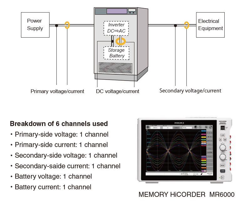
Standard evaluation of a single-phase-type UPS
During operational testing of the UPS, the HiCorder is set up to record, and the voltage level is cut or lowered on the stabilized AC power supply by the engineer. The HiCorder simultaneously records the voltage and current of waveforms at the following points: the primary-side, secondary-side, and internal power storage device (battery). These waveforms can then be used to verify the behavior of the electricity supplied to the facility/equipment (secondary side) in relation to the momentary power anomalies and after power restoration. In addition, recording voltage and current across the battery makes it possible to verify proper current levels and voltage levels under operating conditions. Furthermore, in the event of a long outage, the large storage capacity of the HiCorder enables recording of the UPS’s voltage until the end of the outage (i.e., the end of UPS operation).
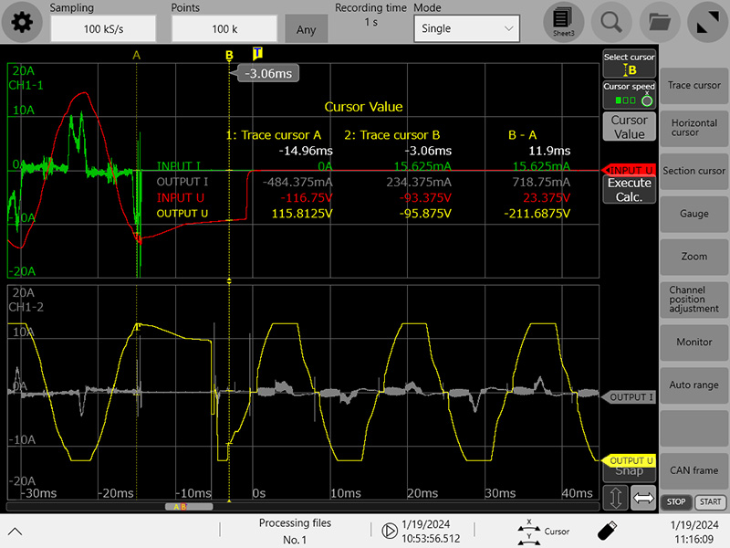
Example waveforms of primary and secondary voltages during UPS operation
2. Versatile operational testing with Hioki HiCorder
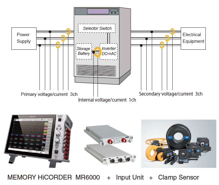
Evaluating 3-phase parallel-processing power supply UPSs
Testing a 3-phase UPS entails measuring more channels than a standard on-line inverter-based system (single-phase). In contrast to the standard on-line inverter-based system, parallel processing UPS systems (designed to deliver superior efficiency and quality) are an example of such a 3-phase UPS. The measurement points for this type of UPS are also the inverter input, primary side, and secondary side. However, the main difference from single phase UPSs—as one may guess—is that the primary and secondary sides each have 3 lines. As with the single phase UPS, the HiCorder records the correlation of current and voltage at these points during system operation. The HiCorder’s simultaneous, multi-point measurement can help analyze power supply quality. This insight can be used for preventative maintenance as well as enlighten UPS developers as to points of improvement.
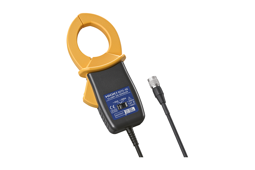
Because parallel processing UPS systems can provide an uninterrupted switchover to power from the inverter, any testing setup must be able to record high-speed phenomena. Measuring instruments must implement high-speed recording on the order of 10 μs (100 kHz sampling), including for phenomena such as power anomalies caused by grid-side noise and harmonics. In addition, noise and harmonics- anomalies necessitate the accurate capture of current waveforms. Hioki’s clamp sensors with high sensitivity and wideband frequency characteristics can do just that. By offering Memory HiCorders and an extensive line of clamp sensors, Hioki provides solutions in 3-phase UPS testing.
Main measurement instrumen
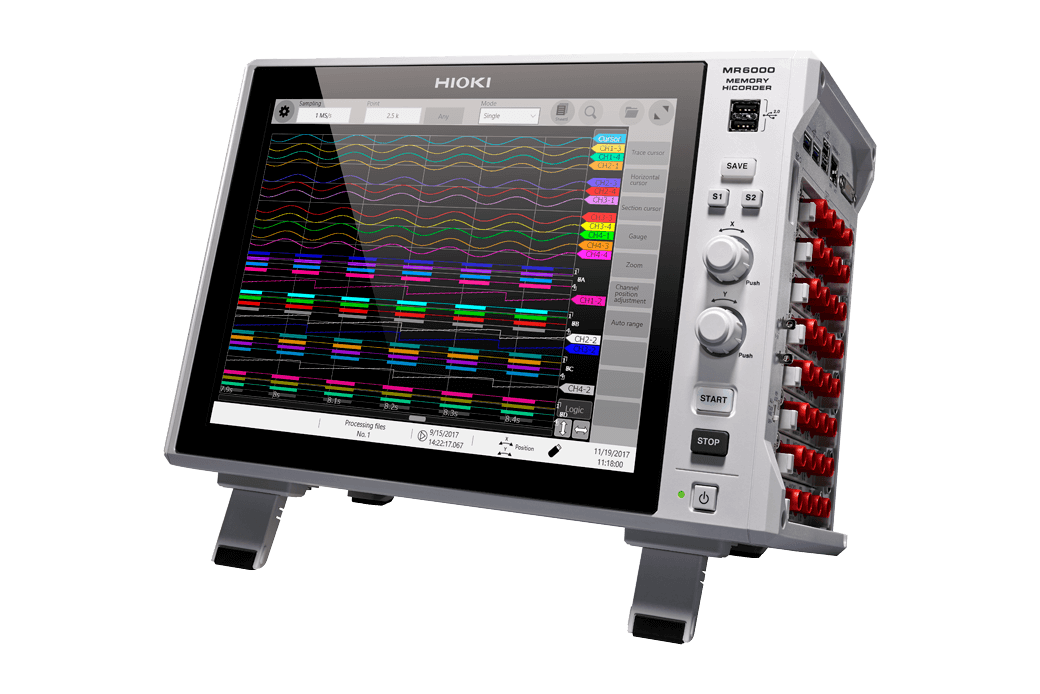
Recorder MEMORY HiCORDER MR6000
Input module ANALOG UNIT 8966 × 4 slots
Input cable CONNECTION CORD L9197 × 7
Input module 3CH CURRENT UNIT U8977 × 3 slots
Current sensor CLAMP ON SENSOR 9272 x 6 (for AC)
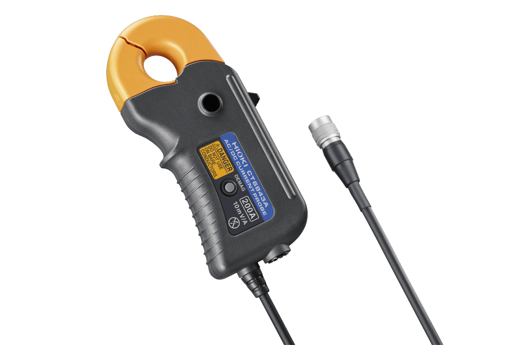
Current sensor AC/DC CURRENT PROBE CT6843A x 1
*The figure on the left provides one example(simultaneous measurement of 7 voltage channels and 7 current channels). The actual setup varies with the system being measured (simultaneous measurement of 7 voltage channels and 7 current channels).
AC current probes that don’t require a power supply are also available in Hioki’s line of current sensors/probes. It’s important to select the most appropriate sensor for each measurement application and location.
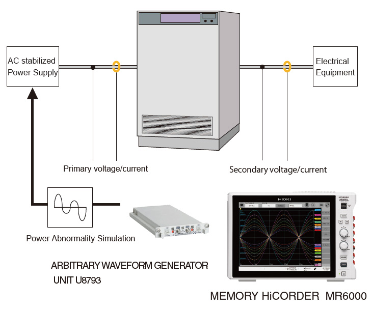
Using a HiCorder to simulate power anomalies and test UPS operation
By attaching an Arbitrary Waveform Generator Unit U8793 to a Memory HiCorder, you can have total control over the waveform of the simulated grid (with the same HiCorder used to measure). The signal is amplified with the stabilized AC power supply to bring it to the correct strength. All anomaly simulations that are needed to ensure reliable UPS operation can be generated in this way. A few examples of anomalies programmed by an engineer (though not in any way an exhaustive list) are momentary voltage dips, momentary outages, and harmonic noise.
In addition to tailor-making waveforms from scratch, the waveform creation software included with the Arbitrary Waveform Generator Unit allows the engineer to take recorded waveforms and use them as-is or altered as desired. This saves time and effort that would otherwise be spent on designing waveforms from scratch.
After setting the waveform you wish to simulate from the Memory HiCorder, it is then amplified with the stabilized AC power supply and sent to the UPS for testing. Simultaneously, the voltage and current of the primary side, secondary side and inverter are measured. This simultaneous measurement of tailor-made waveforms enables testing under conditions that more closely approximate real-life operation of the UPS.
Main measurement instrumen
Recorder MEMORY HiCORDER MR6000
Output module ARBITRARY WAVEFORM GENERATOR UNIT
U8793 × 4 slots
Output cable CONNECTION CABLE L9795-01 × 1
Input module ANALOG UNIT 8966 × 1 slot
Input cable CONNECTION CORD L9198 × 2
Input module 3CH CURRENT UNIT U8977 × 1 slot
Current sensor CLAMP ON SENSOR 9272 x 2
*The figure on the left provides one example. The actual setup varies with the system being measured.
It’s important to select the most appropriate sensors, modules/units, and cables for each measurement application and location.
Inverter control signal analysis
Adding just one more measuring point—the inverter’s control signal wire—to the operational test, can further deepen the analysis of a UPS’s operation. By measuring the voltage of the inverter’s control signal, one can confirm that the inverter responds fast enough to power anomalies from the primary-side.
Observing the waveform of the inverter’s control signal can aid in trouble-shooting in maintenance and offer further insights into potential improvements in the inverter’s interoperation with the UPS’s other components and functions. Best of all, the measurement can be done at the same time as the standard UPS operational testing without having to set up a separate experiment. It is worth noting that the memory HiCorder’s high speed sampling uniquely qualifies it for analyzing the inverter’s control signals. The high sampling rate is necessary because the signal controls themselves are high-speed in order to quickly respond to power anomalies in order to smoothly switch over to UPS power.
This is just one more example of the Memory HiCorder’s versatility. It’s many measurement modules, vast large lineup of compatible current sensors and voltage probes, large number of channels, and software analysis operators (this list can actually be much longer) make it ideal for a variety of analyses, including UPS operation.
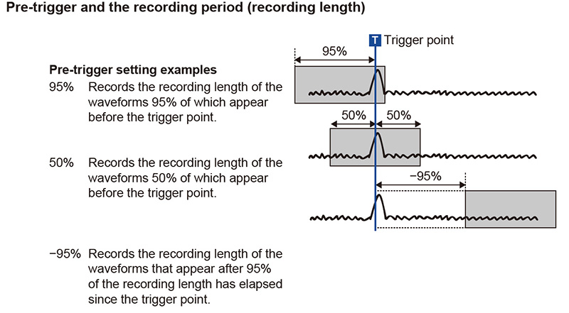
3. Trigger function
To capture conditions during momentary dips and outages efficiently and without wasting resources, Hioki recommends configuring the recorder with triggers and “pre-triggers” for starting recording.
With typical trigger functions, momentary anomalies such as voltage drops can’t be set as triggers (to start measurement). Moreover, even if you could set such an anomaly as a trigger to start recording, you wouldn’t be able to capture the actual anomaly of interest since recording would have started after it occurred.
However, Hioki’s Memory HiCorder solves both of these problems with its trigger and “pre-trigger” functions. The HiCorder’s trigger function allows you to use voltage drops as a trigger. Additionally, its pre-trigger function lets you record phenomena immediately prior to a given trigger. These capabilities are extremely useful in operational and evaluation testing since they let you record multiple parameters on a single time axis before and after anomaly detection. In other words, you can set your HiCorder to record right before, during, and after the UPS supplies its power.
The Memory HiCorder MR6000 allows both voltage dips as triggers and pre-triggers. Detailed trigger settings can be made for multiple channels with “and” and “or” conditions.
Outline of unique benefits provided by the Memory HiCorder MR6000
- Thanks to its fully isolated measurement channels, Hioki’s Memory HiCorders let you connect to both the UPS’s primary and secondary side without worrying about dangers of malfunction and electrocution while also providing outstanding noise resistance in locations in the field.
- High-speed sampling and long memory mean you can record high-speed phenomena over an extended period of time, including inverter output waveforms, harmonics, and noise. An extensive line of input modules means you can add modules and channels later as needed for the system being measured.
- The ability to simultaneously record a large number of channels lets you easily check for correlations between parameters.
- An extensive line of input modules means you can add modules and channels later as needed for the system being measured.
- Hioki has developed a large number of high-sensitivity, wideband sensors for DC and AC currents so that customers can choose the most appropriate sensor for each application. These products also offer unique advantages in terms of ease of use, with some models designed to draw power for operation from the input module to simplify the connection process.
For more information about this product, please visit the MR6000 product web page.
For inquiries such as quotes, demonstrations, and trial usage, please use Hioki’s contact form for a personalized reply from your closest or most appropriate Hioki representative.