Measuring volume resistivity and surface resistivity of conductive materials using the four-point probe method
The 4-point probe method can be used to measure volume resistivity, surface resistivity, and conductivity.
Highlights
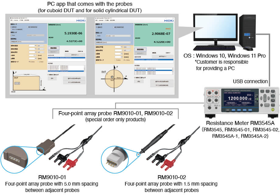
The 4-point probe method is a measurement technique based on the Kelvin 4-wire method (one pair of source send/receive probes and one pair of sense probes), using a 4-point array probe with highly precise pin pitch and placement. With this setup, RCF (Resistivity Correction Factor) calculations are used to determine is used to calculate volume resistivity and surface resistivity (sheet resistance), and conductivity. This 4-point probe resistivity measurement is supported by Hioki’s Resistance Meter RM3545, Resistance Meter RM3545A, 4-point array probe, and dedicated PC application software.
- Hioki offers 4-point array probes in two variants: with probe spacing of 5.0 mm and 1.5 mm.*
- Two types of PC application software are available: one for cuboid DUTs and another for disk-shaped/solid-cylindrical DUTs.
- Measurement parameters include volume resistivity (Ω・m), surface resistivity (Ω/sq), conductivity (S/cm), and resistance (Ω).
- The application software displays the values calculated based on the user-input DUT dimensions and measurement position coordinates.
- Convenient software functions include a probing position guide, a measurement history, and outputting measurement results as a CSV file.
- High accuracy resistivity meter leads to highly accurate volume resistivity.
*: When using the JIS K 7194-compliant measurement mode, the probes that can be used are limited to those with a pin spacing of 5.0 mm. JIS K 7194-1994 "Testing method for resistivity of conductive plastics with a 4-point probe array" is a Japanese Industrial Standard established by the Japanese Standards Association Group and specifies that the distance between adjacent probe pins should be 5.0 mm.
System components
PC software included with the probes (for cuboid DUTs or disk-shaped/solid cylindrical DUTs)
Measurement run-time environment: .NET Framework 4.6.1 or a compatible version.
Note: Please download and install the .NET Framework from Microsoft’s official support website.
4-point Array Probe Resistivity Meter Application Software
Recommended operating environment:
| Supported Operating system | Windows 10 Pro (32/64-bit) or Windows 11 Pro (64-bit) |
|---|---|
| CPU | Intel® Core™ i7, 2.4 GHz, 4 cores or better |
| Memory | 8 GB RAM or more (minimum 4 GB available) |
| Display | 1050 × 1050 pixels or higher, with 32,768 colors or more |
| Hard disk | At least 2 GB of free disk space |
| Communication interface | USB 2.0 interface (virtual COM port) |
| Run-time execution environment | .NET Framework 4.6.1 or a compatible version |
Measurement conditions for cuboid DUT applications (measurement mode: Normal)
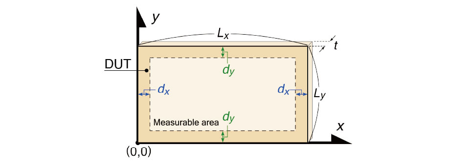

Probe Head Orientation
Place the probe head on the sample so that the four tips are aligned on a straight line parallel to the x-axis.
The measurable area is calculated/shown with the contact point as the center of the probe head.
Set the DUT dimensions and probe conditions. The values for the probe settings can accept 5 significant digits and up to 2 decimal places.
1. DUT length
Enter the DUT length of the long side.
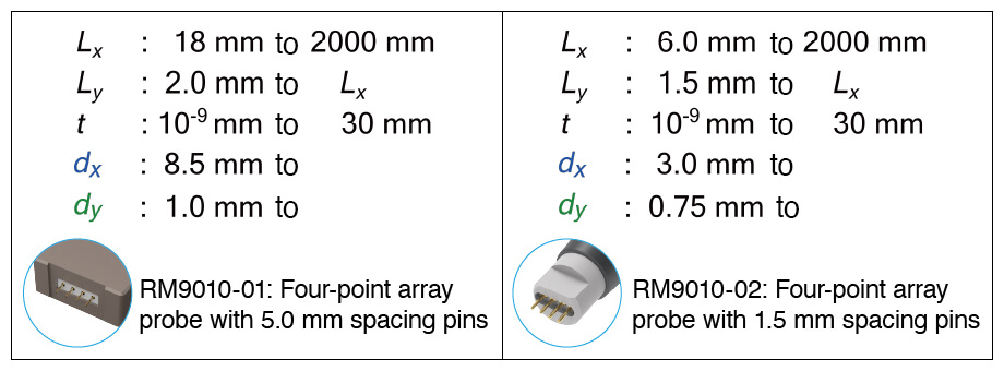
Settable range
- RM9010-01: 18 mm to 2000 mm
- RM9010-02: 6.0 mm to 2000 mm
2. DUT width
Enter the DUT width of the short side.
Settable range
- RM9010-01: 2.0 mm to the length above
- RM9010-02: 1.5 mm to the length above
3. DUT thickness
Enter the DUT thickness.
Settable range
- RM9010-01: 10-9 mm to 30 mm
- RM9010-02: 10-9 mm to 30 mm
4. X-coordinate
Enter the x-coordinate of the probing position. Enter the center coordinate of the probing head.
Settable range
- RM9010-01: Enter a coordinate within the DUT and 8.5 mm or more inward from its short side.
- RM9010-02: Enter a coordinate within the DUT and 3.0 mm or more inward from its short side.
5. Y-coordinate
Enter the y-coordinate of the probing position. Enter the center coordinate of the probing head.
Settable range
- RM9010-01: Enter a coordinate within the DUT and 1.0 mm or more inward from its long side.
- RM9010-02: Enter a coordinate within the DUT and 0.75 mm or more inward from its long side.
Measurement conditions for disk-shaped/solid cylindrical DUTs (measurement mode: Normal)
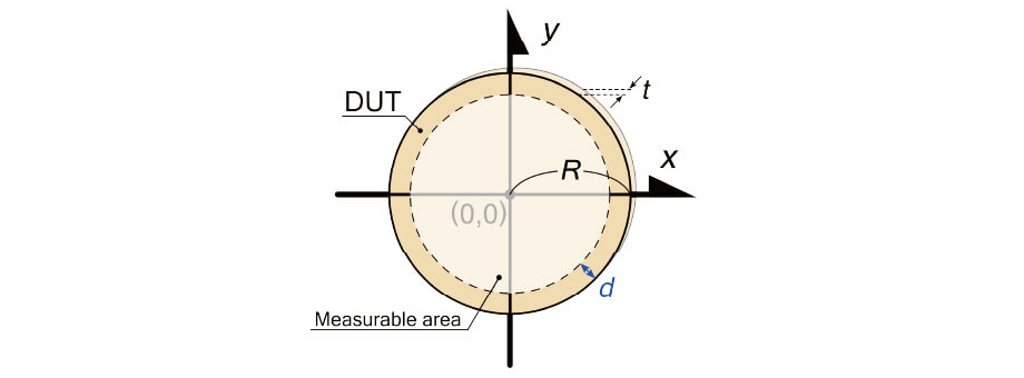

Probe Head Orientation
Place the probe head on the sample so that the four pins are aligned on a straight line parallel to the x-axis.
The measurable area is calculated/shown with the measurement point as the center of the probe head.
Set the DUT dimensions and probe conditions. The values for the probe settings can accept 5 significant digits and up to 2 decimal places.
1. DUT radius
Enter the DUT radius.
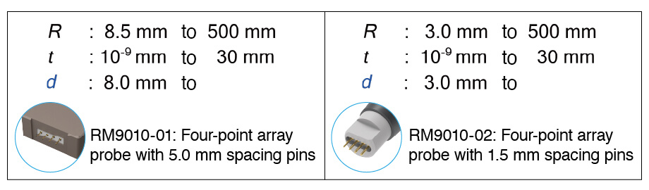
Settable range
- RM9010-01: 8.5 mm to 500 mm
- RM9010-02: 3.0 mm to 500 mm
2. DUT thickness
Enter the DUT thickness.
Settable range
- RM9010-01: 10-9 mm to 30 mm
- RM9010-02: 10-9 mm to 30 mm
3. (x-y) coordinates
Enter the (x-y) coordinates of the probing position. Enter the center coordinate of the probing head.
Settable range
- RM9010-01: Enter (x-y) coordinates of 8.0 mm or more inward from the edge of the DUT.
- RM9010-02: Enter (x-y) coordinates of 3.0 mm or more inward from the edge of the DUT.
Settable resistance range and applied current with the application software
The resistance measurement range/measurement current pairs are as follows. (1000 µΩ, 1 A: RM3545A only)
| 10 MΩ, 1 μA | 1000 kΩ, 10 μA | 100 kΩ, 100 μA | 10 kΩ, 1 mA | 1000 Ω, 1 mA | 100 Ω, 1 mA |
| 10 Ω, 1 mA | 1000 mΩ, 10 mA | 100 mΩ, 100 mA | 10 mΩ, 1 A | 1000 µΩ, 1 A |
Four-point Array Probe model RM9010-01/RM9010-02
Model RM9010-01: Specifications
| Probe material | Base material: Beryllium copper Plating: Gold (nickel undercoating) |
|---|---|
| Probe diameter | Approx. 0.77 mm |
| Probe pin tip shape | Spherical |
| Probe array | Collinear |
| Spacing between adjacent pins | 5.0 mm ±0.1 mm (with every pin thrust against an object) |
| Insulation resistance between adjacent probes | 10 GΩ or more for an applied voltage of 25 V at an ambient temperature of 23℃(73.4℉) and relative humidity of 35% RH |
| Pin spring force (per spring) | 1.25 N ±0.25 N (with every pin thrust against an object) |
| Maximum rated terminal-to ground voltage | 30 V AC RMS or less, 42.4 V AC peak or less, 60 V DC or less |
| Rated current | 3 A AC/DC continuous |
| Operating temperature and humidity range | 0℃to 40℃(32℉ to 104℉), 80% RH or less (non-condensing) |
| Storage temperature and humidity range | -10℃to 50℃(14℉ to 122℉), 80% RH or less (non-condensing) |
| Operating environment | Indoors, pollution degree 2, operating altitude: Up to 2000 m (6562 ft) |
| Length | About 1500 mm (59.06 in.) |
| Weight | About 200 g (7.1 oz.) |
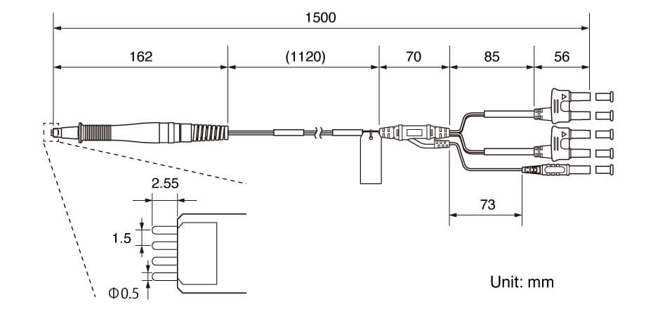
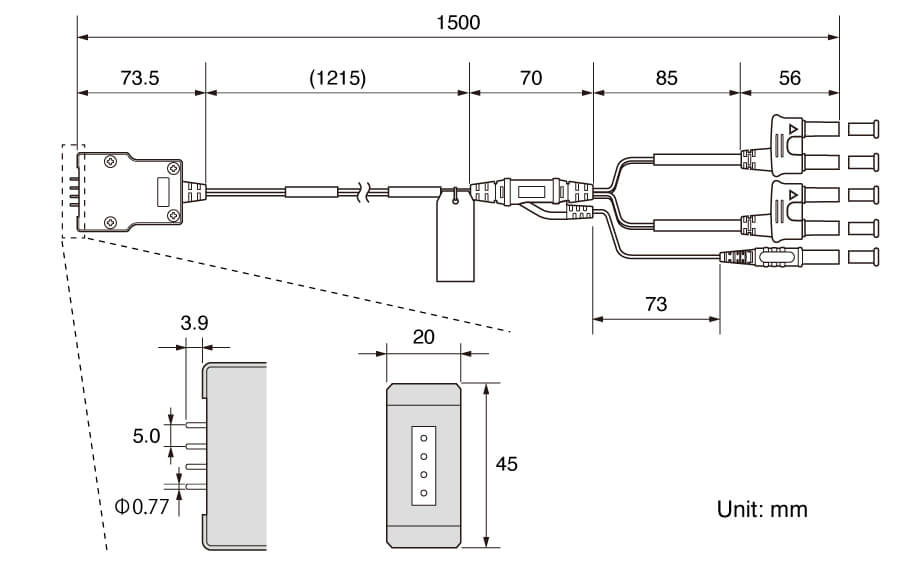
Model RM9010-01: Outline drawing
Model RM9010-02: Specifications
| Probe material | Base material: Beryllium copper Plating: Gold (nickel undercoating) |
|---|---|
| Probe diameter | Approx. 0.5 mm |
| Probe pin tip shape | Spherical |
| Probe array | Collinear |
| Spacing between adjacent pins | 1.5 mm ±0.1 mm (with every pin thrust against an object) |
| Insulation resistance between adjacent probes | 10 GΩ or more for an applied voltage of 25 V at an ambient temperature of 23℃(73.4℉) and relative humidity of 35% RH |
| Pin spring force (per spring) | About 0.85 N (with every pin thrust against an object) |
| Maximum rated terminal-to ground voltage | 30 V AC RMS or less, 42.4 V AC peak or less, 60 V DC or less |
| Rated current | 1.5 A AC/DC continuous |
| Operating temperature and humidity range | 0℃to 40℃(32℉ to 104℉), 80% RH or less (non-condensing) |
| Storage temperature and humidity range | -10℃to 50℃(14℉ to 122℉), 80% RH or less (non-condensing) |
| Operating environment | Indoors, pollution degree 2, operating altitude: Up to 2000 m (6562 ft) |
| Length | About 1500 mm (59.06 in.) |
| Weight | About 150 g (5.3 oz.) |
Model RM9010-02: outline drawing