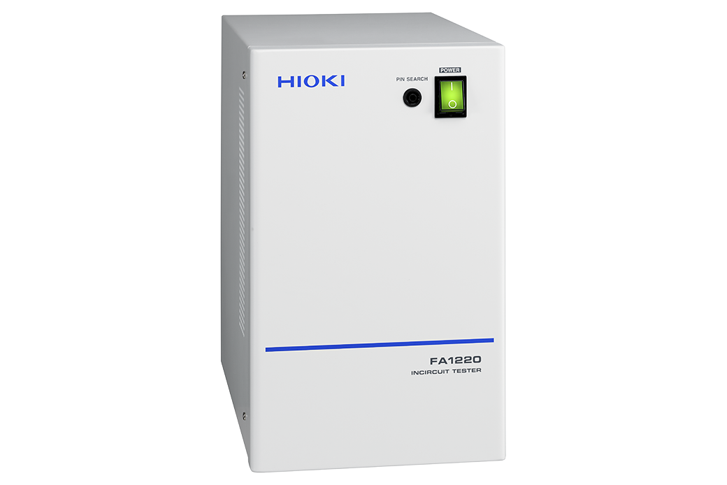
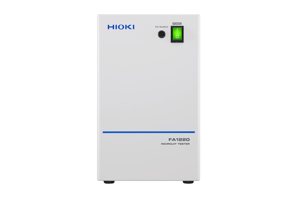
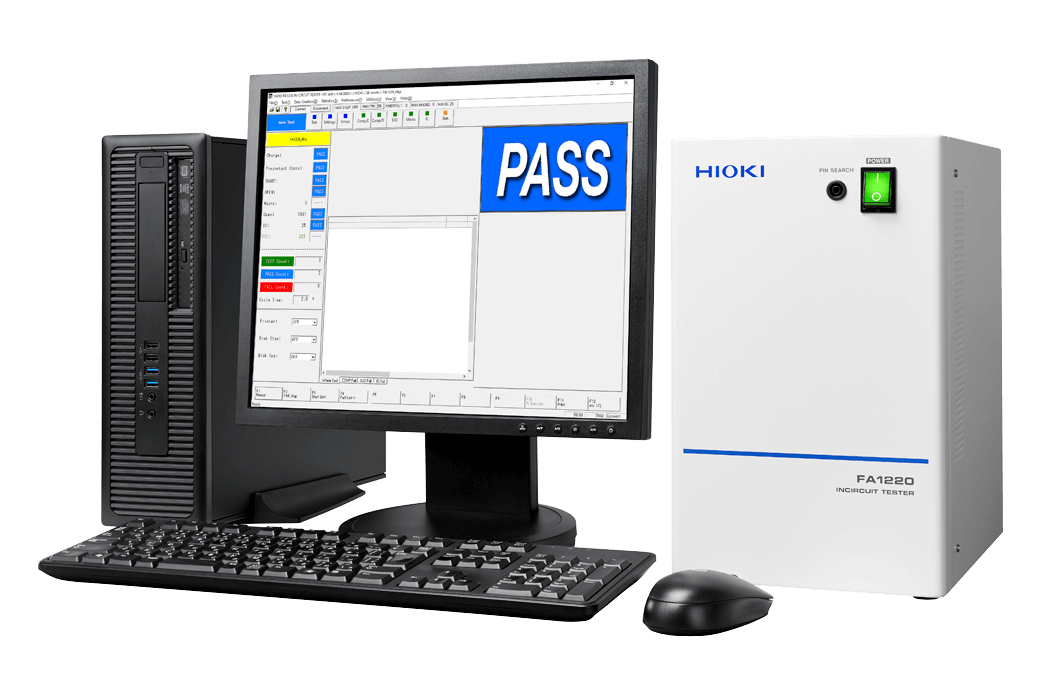
IN-CIRCUIT TESTER FA1220
Embed into Existing Equipment to Conduct Functional Tests of Individual Electronic Circuit Board Components or While Mounted on PCBs
Hioki PCB and substrate inspection equipment leverages our core competency in high precision component testing. The FA1220 an embeddable PCB measuring component that provides extensive function testing capabilities to complement existing automatic testing equipment.
Key Features
- Functionality has been consolidated in a single, desktop tower that can be easily embedded in existing equipment
- Extensive function testing
- Electrolytic capacitor and IC reverse insertion detection
- Macro-testing function to increase test efficiency
- Four-terminal low-resistance measurement for stable measurement of low resistance
Model No. (Order Code)
| FA1220 | Main unit only |
|---|
•Data from the legacy 1101 and 1102 cannot be converted for use by the 1220 (FA1220) because Hioki is unable to supply computers that can run the 1137 Support Software.
•Data compatibility between the FA1220/FA1221 and legacy products (1220-00/-01/-02/-11/-50/-51/-52/-55): Although data created for legacy products can be used, such data is not fully compatible with the FA1220/FA1221. It may be necessary to perform stray capacitance acquisition, wiring resistance acquisition, S/O data acquisition, IC data acquisition, and component test debugging. In particular, it may be necessary to reacquire stray capacitance in applications that involve measurement of minuscule capacitance values.
FA1220 Specifications Overview
| Number of test points | Max. 1024 pins (Can be added in blocks of 128 pins.) Standard : 0 pins (Scanner boards are sold as options.) |
|||||
|---|---|---|---|---|---|---|
| Number of test steps | Round-robin short/open data : 1024 pins Component data : Max. 10000 steps Macro data : 1024 pins/1024 steps (regardless of number of pins) IC data : 500 steps (max. 1024 pins/step) Charge data : 40 sets Pin contact data : 1024 pins Group data : 255 groups |
|||||
| Test parameters and measurement ranges | Round-robin short/open : | 4 Ω to 400 kΩ (Default: 40 Ω) | ||||
| Macro testing (impedance) : | 1 Ω to 10 MΩ | |||||
| Component tests : | Possible | |||||
| IC reverse insertion detection : | Possible | |||||
| Measurement unit | DC voltmeter : | 800 μV f.s. to 25 V f.s., 8 ranges | ||||
| DC ammeter : | 100 nA f.s. to 250 mA f.s., 9 ranges | |||||
| AC ammeter : | 10 μArms f.s. to 10 mA rms f.s., 4 ranges | |||||
| Macro test : | Ammeter 10 μ / 100 μ / 1 m / 10 m Arms, 4 ranges | |||||
| Scanner unit (*2) | Software used : | Analog switch (Scanner board E4201, E4202) | ||||
| Number of channels : | 128 channels/board (2-/4-terminal switchable) | |||||
| Input protection : | ±15 V / ±0.5 V (Batch-configurable, Scanner Board E4201 / E4202 only) | |||||
| External I/O (*2) | Using I/O Board E4220 (*1) : 60 inputs, 56 outputs | |||||
| Control unit | External computer (sold separately) FA1220: Real-time operating system, LAN for PC connectivity (10 / 100 ×1 port) |
|||||
| Power supply | 100 to 240 V AC (±10%), single-phase, 50 Hz / 60 Hz, max. 260 W (with full 1024 pins of scanner boards) | |||||
| Dimensions and mass | 200 mm (7.87 in) W × 323 mm (12.72 in) H × 298 mm (11.73 in) D, 10 kg (352.7 oz) | |||||
| Accessories | Instruction manual ×1, Test leads ×1, Power cord ×1, Metal fittings ×1, Installation CD ×1 | |||||
- *1:Hioki plans to update the FA1220/FA1221 to provide functionality for configuring the I/O Board E4220.
- *2:Sold separately.
Testing data creation (2)
1220 DATA COMPOSITION SOFTWARE 1137-05
For editing data on a computer


