Testing varnish impregnation state in a motor with an LCR meter
Differences in the varnish impregnation state of motors can be clearly ascertained by measuring dielectric loss tangent δ at a low frequency.
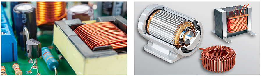
Motors are one of the most common devices that convert electrical energy into mechanical energy. They are widely used in various industries, including transportation equipment such as EVs and trains as well as in the heating, ventilation, and air conditioning (HVAC) equipment industries. Since the electrical insulation of motors affects safety, performance, and durability, they must be inspected during manufacturing, maintenance, and repair. The stator, a key motor component, is made by winding insulated wire around an iron core.
Adding insulation paper and applying varnish impregnation treatment* increases the insulation of the coil. In addition to providing insulation, the varnish fills any gaps inside the coil and acts as a barrier against moisture and dust, both of which can contribute to insulation degradation.
There are two types of varnish impregnation treatments: trickle impregnation, in which the coil is immersed in a tank of varnish (which serves as an insulating material), and vacuum impregnation, in which varnish is injected after the coil is subjected to a vacuum.
Effectively ascertaining the quality of impregnation
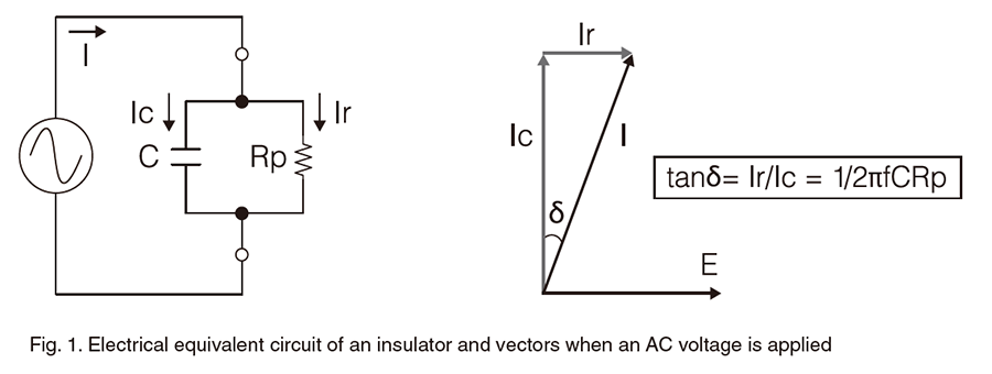
Generally, a tan delta meter (a.k.a. dielectric loss tangent meter ) is used to test the varnish impregnation state of motors. The tan δ (dielectric loss tangent) serves as a numerical indicator for the condition of electrical insulating materials. When an AC voltage is applied to a motor’s insulator (between the coil and ground), dielectric loss occurs. The dielectric loss tangent expresses the extent of this loss.
Tan delta meters make measurements by applying a relatively high voltage at 50 or 60 Hz. Dielectric loss, or loss tangent, can be expressed as follows: tan δ = 1/2πfCRp. In this formula, tan δ increases as the frequency f decreases. In other words, the ability to make measurements at a frequency lower than 50 or 60 Hz would make differences in impregnation state more pronounced, allowing the property to be ascertained even more accurately.
Solution using an LCR meter
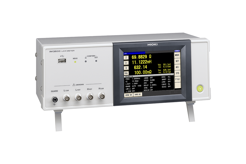
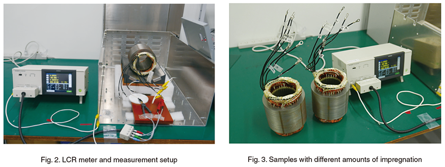
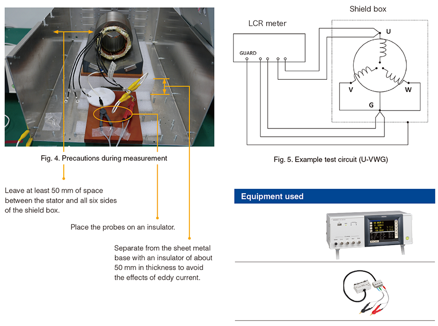
In an experiment performed by Hioki engineers, we prepared two vacuum impregnated stators, one non-defective, and the other defective due to insufficient impregnation. We measured tan δ between the coil and core in each with an LCR meter. The following figures depict that process and present the associated measurement data. Since this high-impedance measurement setup is particularly susceptible to noise, we enclosed the motors in a shielded box and connected the box to the LCR meter’s GUARD terminal. Other steps were also taken to deal with noise, for example closing all six sides of the shield box during measurement.
Measurement data
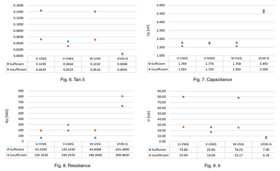
LCR meter settings Measurement frequency: 10 Hz, Measurement signal CV (constant voltage): 5.0 V, Averaging count: 50
We observed significant differences in dielectric loss factor (tan δ), resistance values (insulation resistance Rp), and Ir (insulation resistance). The non-defective samples (with sufficient impregnation) exhibited higher Ir and tan δ values. The increase in varnish quantity reduces the amount of air (which has a low dielectric constant) and therefore decreases the resistance value between electrodes (coil to core, phase to phase). As a result, Ir increases, and the increase in Ir leads to a larger tan δ value.
Observations
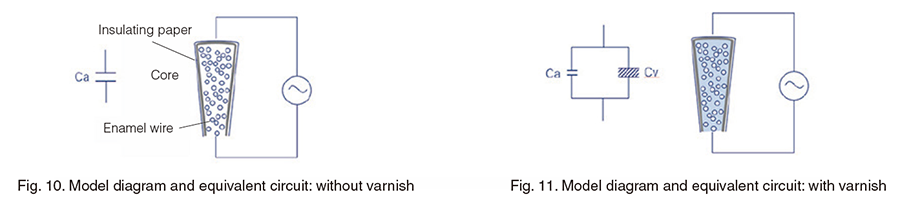
• In the model diagram and equivalent circuit without varnish (fig. 10), the core and coil act as electrodes, insulated by air and insulating paper.
• The combined capacitance of air and insulating paper is denoted as Ca.
• When varnish is present (fig. 11), the varnish also acts as an insulating material, reducing the amount of air. This results in a combined capacitance composed of the reduced capacitance Ca (air) and the capacitance of the varnish Cv.
• Capacitance is given by the formula C = ε * S / d (F). Assuming the electrode area (S) and the distance between electrodes (d) remain constant, capacitance is determined by the dielectric constant (ε).
• Air has a dielectric constant of 1. Varnish has a minimum dielectric constant of 2.8. The higher dielectric constant of the insulating material can be inferred to cause both capacitance and tan δ to increase.
• In UVW-G, where the electrode area S is large, the differences in tan δ and Ir are minimal, but the results for Rp clearly differ.