ALDAS-Mini: EIS MEASUREMENT SYSTEM
Visualizing Dynamic Characteristics of Electrolysis Cells or Fuel Cells & Optimizing Operational Efficiency
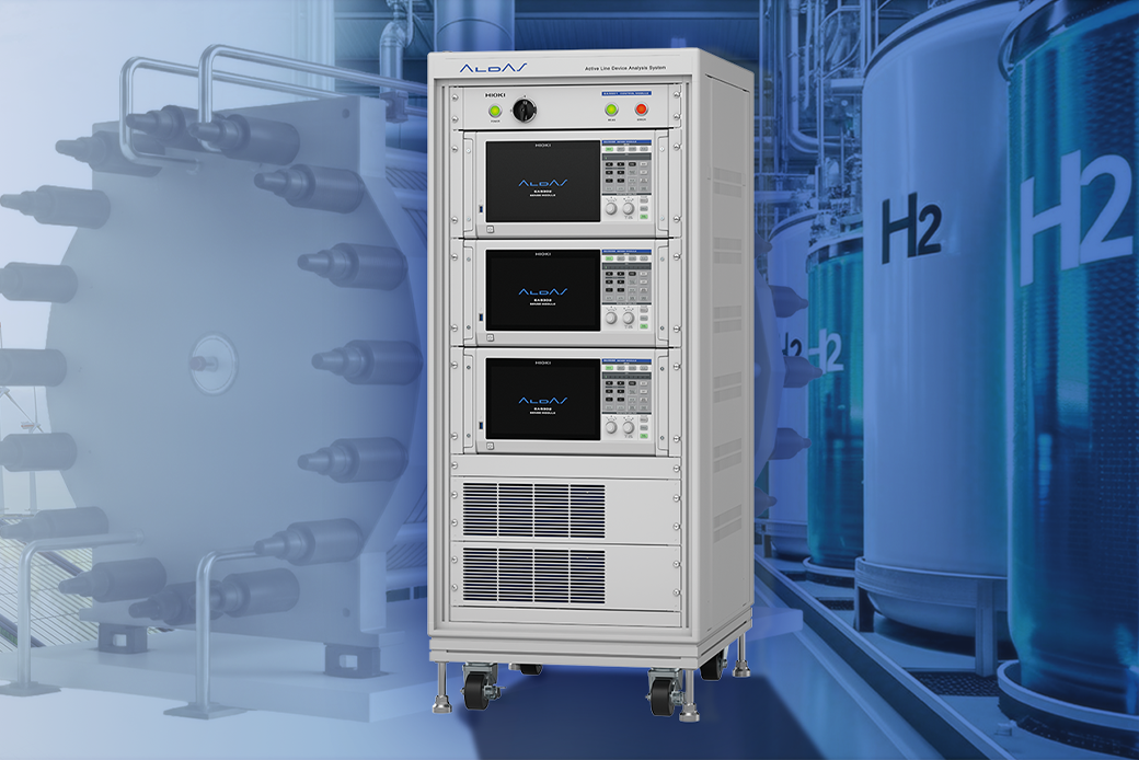
The ALDAS-Mini (Electrolysis Cell Analyzer) is a compact, high-performance solution designed to accelerate R&D in electrolysis cell technology. Engineered for precision, it enables advanced analysis of electrolysis cells, playing a pivotal role in the global transition to sustainable, hydrogen-based energy systems.
Electrolysis cells are essential for generating clean hydrogen, a critical component in achieving carbon neutrality. The ALDAS-Mini empowers researchers and engineers to optimize operational parameters, reduce costs, and improve efficiency by delivering insights into cell performance under operating conditions. This system supports the pursuit of cleaner energy solutions and a sustainable future.
Product Video
This video will introduce the methods for connecting this system to the measurement target, the configuration procedures, and some measurement examples.
Key Features
- Innovative impedance measurement: max. 2000 A electrolysis or load current
- Ease of integration: requiring no modifications to existing systems
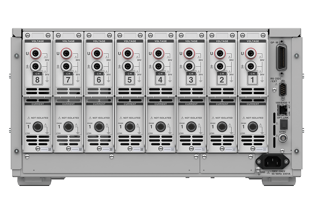
- Simultaneous multi-cell measurement: up to 8 cells in a stack
- High-precision measurements in noisy environments: consistent and reliable results
- Wide compatibility: supports electrolysis cell types including PEM, SOEC, AEM, AWE, etc.
Model No. (Order Code)
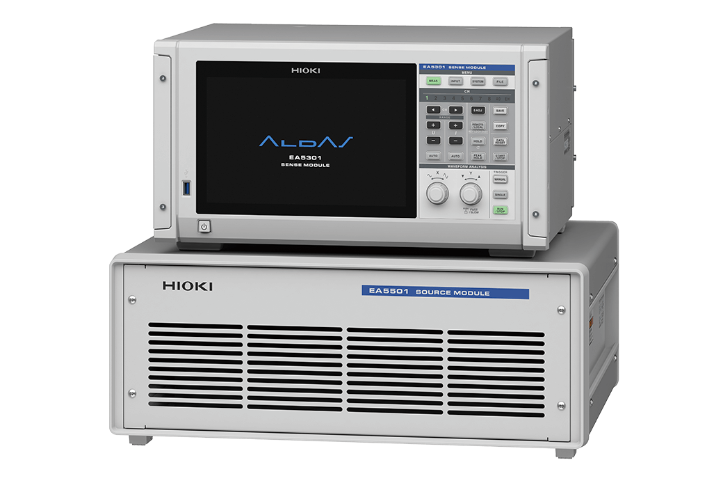
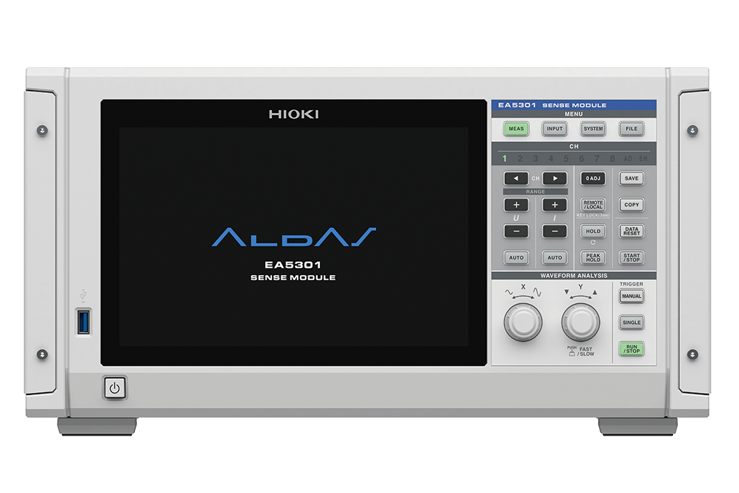
| EA5301-01 | SENSE module 1ch |
|---|---|
| EA5301-02 | SENSE module 2ch |
| EA5301-03 | SENSE module 3ch |
| EA5301-04 | SENSE module 4ch |
| EA5301-05 | SENSE module 5ch |
| EA5301-06 | SENSE module 6ch |
| EA5301-07 | SENSE module 7ch |
| EA5301-08 | SENSE module 8ch |
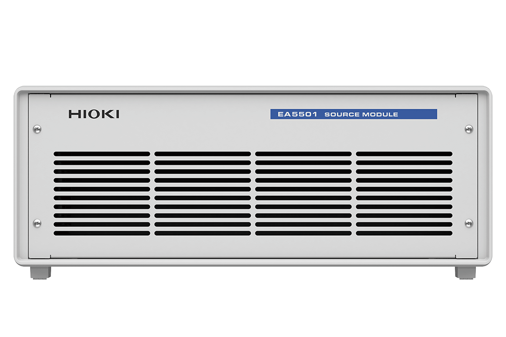
| EA5501 | SOURCE module |
| EA5701 | PC application software |
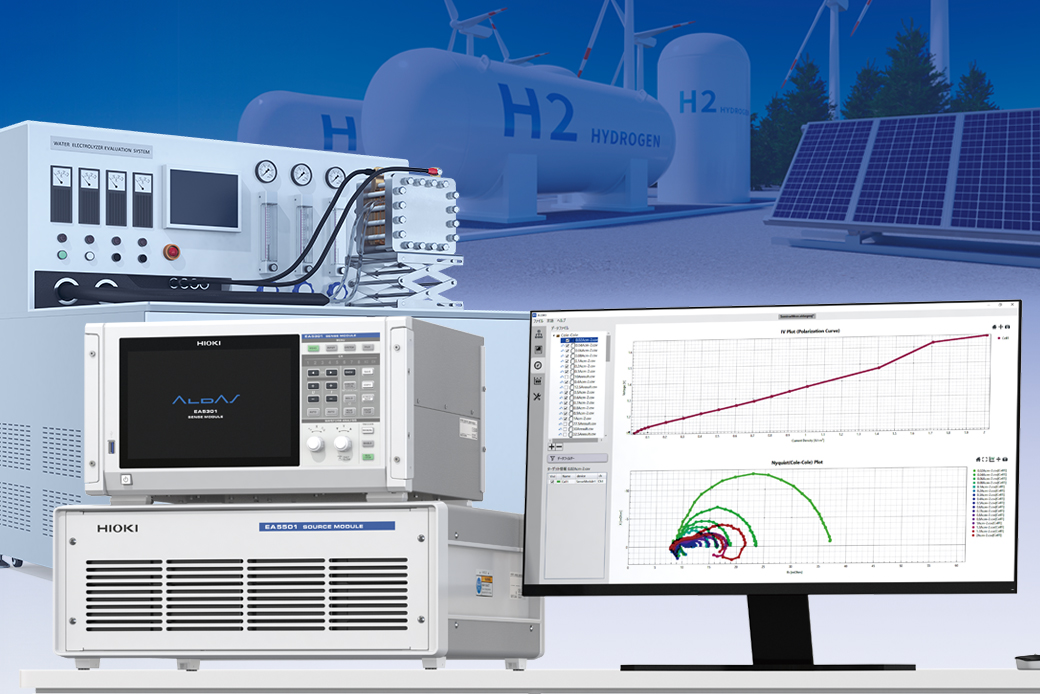
Accelerate electrolysis cell or fuel cell development via high-current operational testing
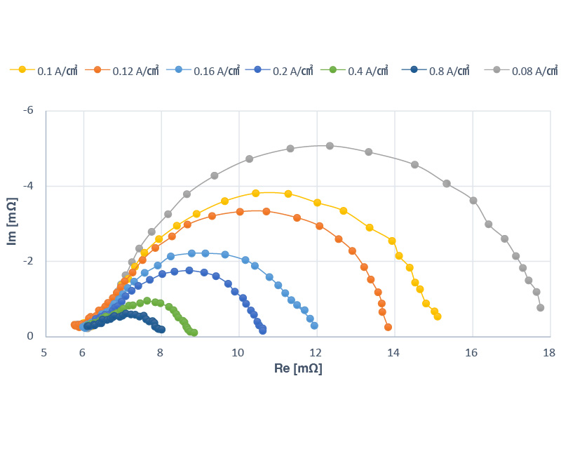
EIS (Electrochemical Impedance Spectroscopy) measurement of electrolysis cells or fuel cell used to face challenges in measuring large cells or cell stacks with high currents. The ALDAS-Mini addresses this issue by enabling EIS measurement for a wide range of cell sizes, from small cells with electrolysis currents or load current of a few amperes to large cells with currents of up to 2000 A.
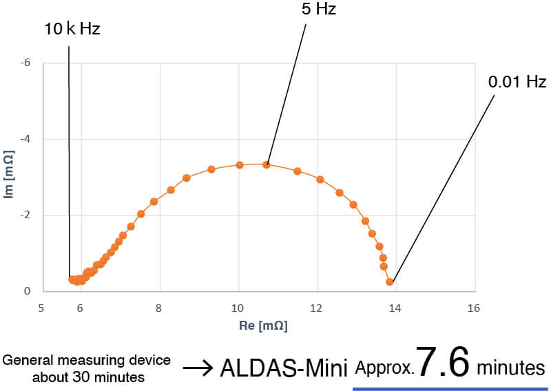
High-speed EIS measurement shortens test cycles
To observe the diffusion resistance region, impedance measurements must be extended to the low-frequency range. However, these measurements pose a challenge as they require a significant amount of time to complete. A typical electrochemical instrument, for instance, can take roughly 30 minutes to run a scan from 10 kHz to 0.01 Hz.
The ALDAS-Mini completes the same measurement in approximately 7.6 minutes*¹ across 8 channels simultaneously. This advantage in speed and parallel measurement capability significantly improves throughput for evaluating electrolysis cells and fuel cell systems.
(*1:Measurement conditions: 10 kHz to 0.01 Hz, 30 points, fast mode)
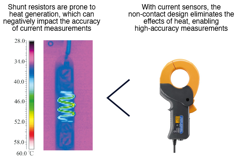
Stable, high-accuracy measurement down to the low-frequency range
Our current sensor method avoids the temperature drift issues common with shunt methods. High precision current measurement ensures stable results with minimal variation, even at low frequencies below 1 Hz.
Designed for seamless setup, requiring no modifications to existing systems
No modification to your electrolysis system is needed to set up the ALDAS-Mini.
Unlike conventional booster-equipped FRA (Frequency Response Analyzer) devices, the ALDAS-Mini operates seamlessly alongside the cells' DC power supplies.
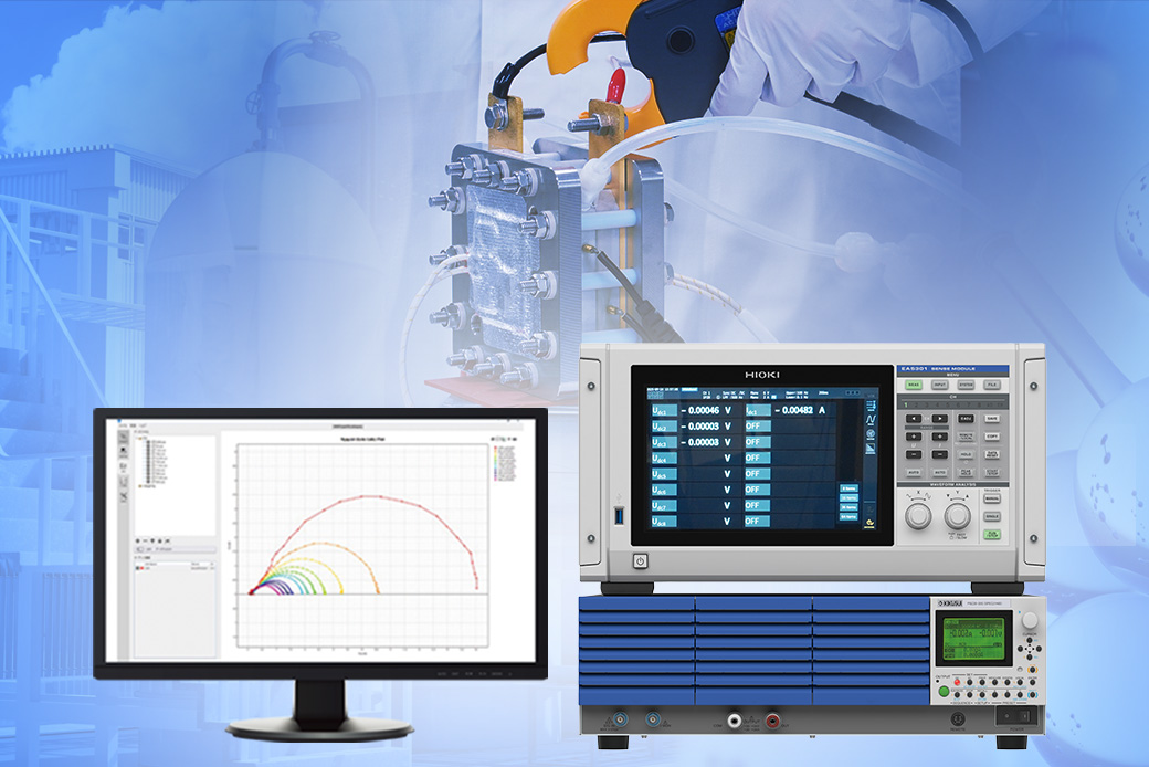
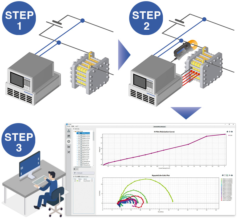
STEP 1: Applied current connection
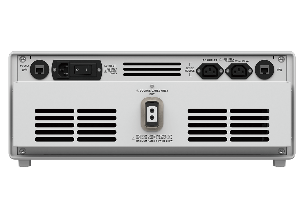
Connect the SOURCE module to the cell’s power source terminal with the SOURCE Cable.
The SOURCE module applies AC current for measurement.
STEP 2: Measurement line connection
Attach the current sensor to measure the current. Then, connect the SENSE cable to the cell to measure the voltage (both connected to the SENSE module).
STEP 3: Start measurement
Start the measurement after configuring the necessary settings in the dedicated PC software.
The I-V curve and Nyquist plot are displayed simultaneously in real-time, with impedance calculated from the measured current and voltage.
Basic specification
| Measurement target | Electrolysis cell, fuel cell, cell stack |
|---|---|
| Measurement parameters | Impedance (R,X,θ,Z), voltage (V), current (I) |
| Measurement modes | Logging Mode, EIS Mode |
| Display modes | Nyquist plot, Bode plot, logging plot |
| Measurement voltage range | 250 mV to 60 V |
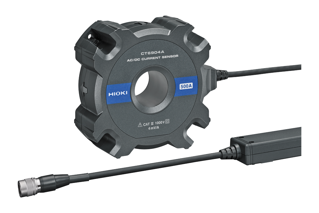
| Measurement current range | 100 mA to 500 A (CT6845A) Maximum 2000 A (depending on the combination of sensors) |
| Max. applied measurement signal | 40 Ap-p (at 5 V) Derating applies for voltages above 5 V |
| Measurement frequency range | 10 mHz to 100 kHz |
| Number of input channels | 1 to 8 channels |
| Dimensions and weight | SENSE Module EA5301 (with 8 channels): approx. 430W × 221H × 361D mm (16.9W × 8.7H × 14.2D in.) (excluding protruding parts), approx. 12.7 kg (28.0 lbs) SOURCE module EA5501: approx. 520W × 197H × 540D mm (20.5W × 7.8H × 21.3D in.) (excluding protruding parts), approx. 27.0 kg (59.5 lbs) (not including cables) |
| Power supply | 100 V to 240 V AC, 50 Hz/60 Hz, 500 VA |
| PC requirements | OS: Windows 11 Interface: wired LAN |
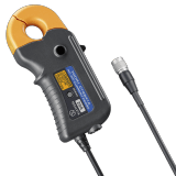
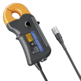
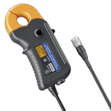
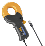
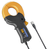
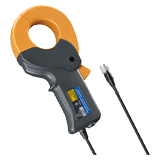
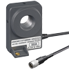
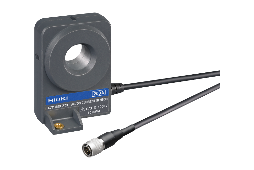
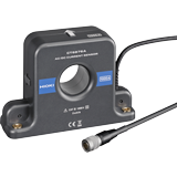
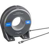
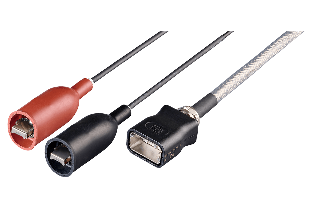
Current sensors (13)
The CT9557 is required when using two or more current sensors.

Connection cables (2)
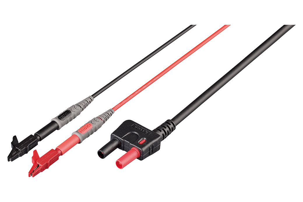
Small alligator clips, 2.2 m (7.2 ft.)
Large alligator clips, 2 m (6.6 ft.)
-
ELECTROLYSIS CELL ANALYZER EA5701
 Test Report
Japanese
Test Report
Japanese
English Ver.01 -
SENSE MODULE EA5301-08
Test Report
Japanese
English Ver.01 -
SENSE MODULE EA5301-07
Test Report
Japanese
English Ver.01 -
SENSE MODULE EA5301-06
Test Report
Japanese
English Ver.01 -
SENSE MODULE EA5301-05
Test Report
Japanese
English Ver.01 -
SENSE MODULE EA5301-04
Test Report
Japanese
English Ver.01 -
SENSE MODULE EA5301-03
Test Report
Japanese
English Ver.01 -
SENSE MODULE EA5301-02
Test Report
Japanese
English Ver.01 -
SENSE MODULE EA5301-01
Test Report
Japanese
English Ver.01 -
ELECTROLYSIS CELL ANALYZER
Instruction Manual
English
Ver.02