Piezoelectric elements
What are piezoelectric elements?
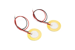
Piezoelectric elements are used in a wide range of applications, including buzzers, sensors, and filters. Since resonant and antiresonant frequencies characterize their impedance/frequency characteristics, an impedance analyzer is the ideal instrument for use in analyzing their characteristics.
Setting example of measurement conditions
| Measurement modes | ANALYZER | |||||||||||||||||||||||||||||
| Parameters | Z-θ | |||||||||||||||||||||||||||||
| Sweep parameter | FREQ | |||||||||||||||||||||||||||||
| Sweep frequency | Set to a range within which the resonant, anti-resonant frequency can be checked. | |||||||||||||||||||||||||||||
| Signal level | Depends on the measurement items | |||||||||||||||||||||||||||||
| Equivalent circuit model | E | |||||||||||||||||||||||||||||
Equivalent circuit of piezoelectric elements
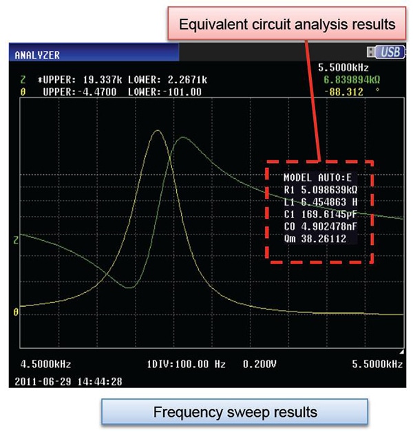
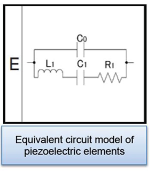
Close to its resonant frequency, a piezoelectric element can be depicted as an electrical equivalent circuit. Specifically, such an element can be depicted as a parallel capacitance CO that is connected in parallel to a series circuit consisting of the series inductance L1, the series capacitance C1, and the series resistance R1.
Actual measurement and analysis
The image describes actual measurement and analysis with an IM3570 and IM9000 (optional equivalent circuit analysis software).
Recommended products
| Model | Frequency | Features | ||||||||||||||||||||||||||||
| IM3590 | DC,1mHz to 200kHz | Analyzer mode (low frequency), equivalent circuit analysis | ||||||||||||||||||||||||||||
| IM3570 IM9000 | DC,4Hz to 5MHz | Frequency sweep with analyzer mode | ||||||||||||||||||||||||||||
| IM3570 | ||||||||||||||||||||||||||||||
| IM7581 | 100kHz to 300MHz | Analyzer mode (high frequency), equivalent circuit analysis | ||||||||||||||||||||||||||||
Measuring resonant frequency and anti-resonant frequency
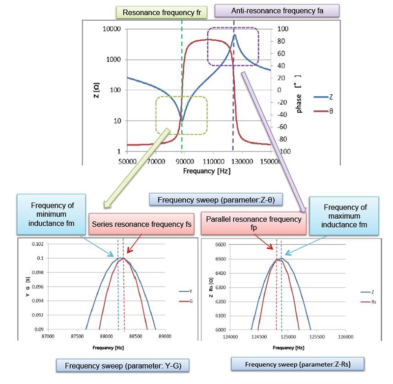
The frequency fm characterized by minimum inductance and the frequency fn characterized by maximum inductance can be calculated from the element’s impedance/frequency characteristics using the instrument’s peak search function. In addition, it is possible to calculate the resonant frequency fr, which is characterized by a phase of 0, and the antiresonant frequency fa.
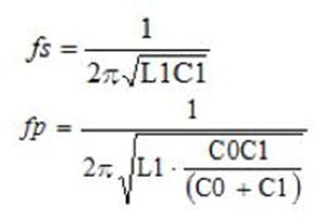
The series resonant frequency fs and the parallel resonant frequency fp can be expressed as shown on the right.
Equivalent circuit analysis
Pass/fail judgments using analyzer mode
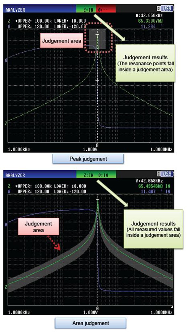
Either of two methods can be used to generate pass/fail judgments when using analyzer mode: peak judgment and area judgment.
Judgement areas can be set as follows.
• A known-good element’s measured value can be used as the reference (±10% of the reference element’s measured value, etc.).
• A user-specified value can be entered (1 k±10%, etc.).

