Working Principle and Characteristics of Zero flux Current Sensors

In this article, we will mainly discuss high-accuracy, wideband current sensor for power measurement and waveform observation using zero flux technology. To learn more about general-purpose current sensors for grid power quality control, which are measured at commercial frequencies (50 Hz and 60 Hz), refer to this article.
More than 50 years have passed since HIOKI launched its first clamp tester in 1971. To achieve high accuracy and broadband performance, HIOKI has sticked to the zero flux method and has developed magnetoelectric conversion technology and typical devices such as fluxgate and Hall elements.
- Learn the working principle of zero flux method current sensors designed for high performance measurement.
- Understand the characteristics of each current sensing method to select the corresponding current sensor that best suits your application.
Major types of current sensors for high performance measurement:
- What is the Zero flux method?
- 1. Zero flux method : Winding Detection (AC)
- 2. Zero flux method : Hall Element Detection (DC/AC)
- 3. Zero flux method : Fluxgate Detection (DC/AC)
- Zero flux method comparison table (features, applications, recommended current sensor)
Major types of current sensors for general-purpose measurement:
How does a magnetic balance current sensor work?
What is the Zero flux method?
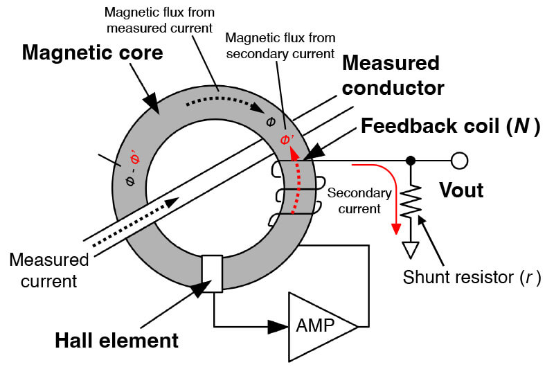
- Note:The explanation below is based on the detection when a Hall element is used.
- 1.A magnetic flux (Φ) is produced inside the magnetic core by the electric current flowing in the conductor being measured.
- 2.A secondary electric current flows to the secondary side of the feedback winding, in order to cancel out the magnetic flux produced inside the magnetic core. (The magnetic flux of the feedback winding is marked as Φ’)
- 3.However, in the low-frequency regions resulting from DC currents, the magnetic flux cannot be cancelled and thus remains in the magnetic circuit. (The remaining magnetic flux in the magnetic core comes out to Φ-Φ’)
- 4.The Hall element detects this remaining magnetic flux (Φ-Φ’). Then, a secondary feedback current is added through an amplifier circuit so as to cancel out the remaining magnetic flux (Φ-Φ’).
- 5. The secondary electric current then flows through the coil and into the shunt resistor (r). This electric current is a sum of the current from the CT effect (current generated by the coil) and the amplifier (feedback current from Hall element detection). This produces a voltage across its terminals. The output voltage is proportional to the measured current.
 Probe output: Hall element detection
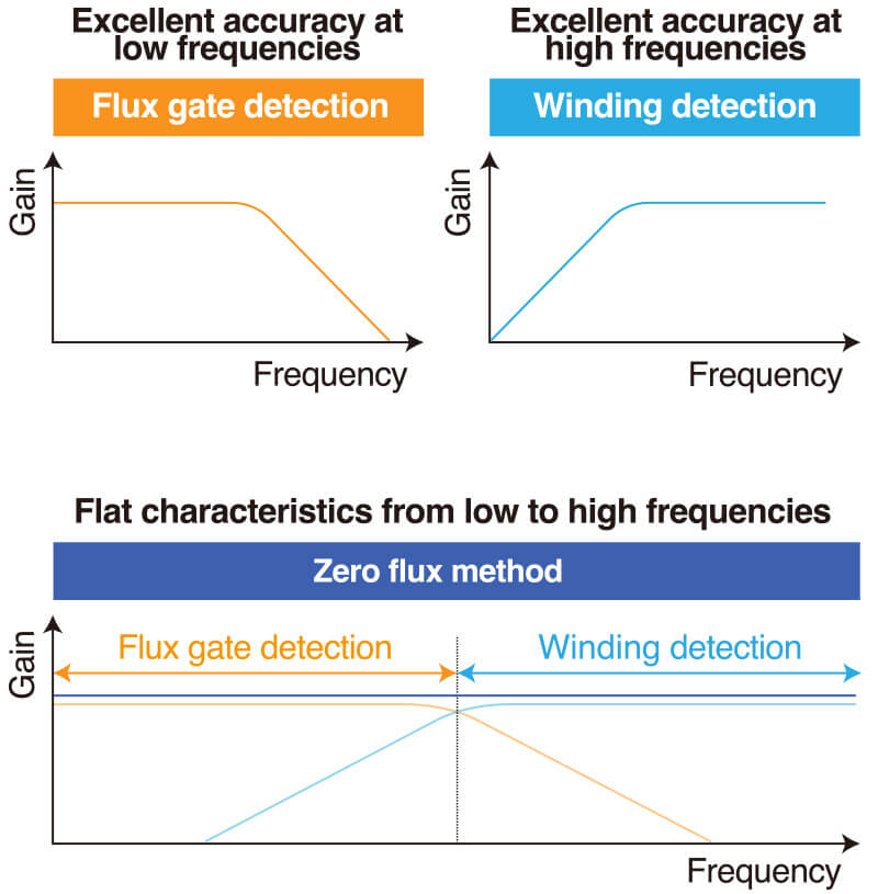 Probe output: Fluxgate Detection
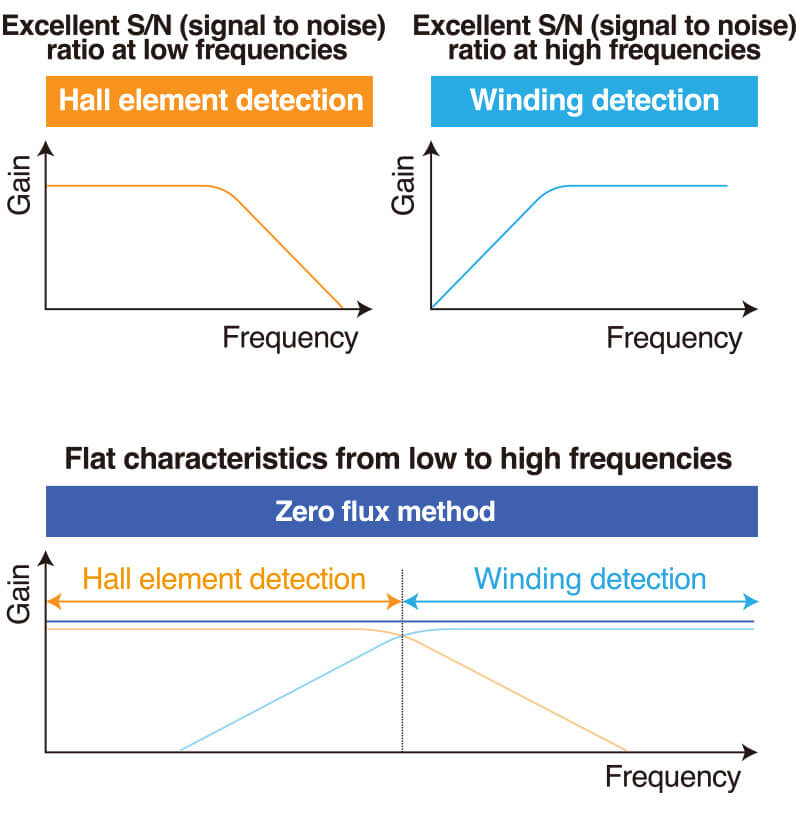
The zero-flux method provides stable and wide-band measurement, from DC to high frequencies.
1. Working Principle of Zero flux method: Winding Detection (AC)
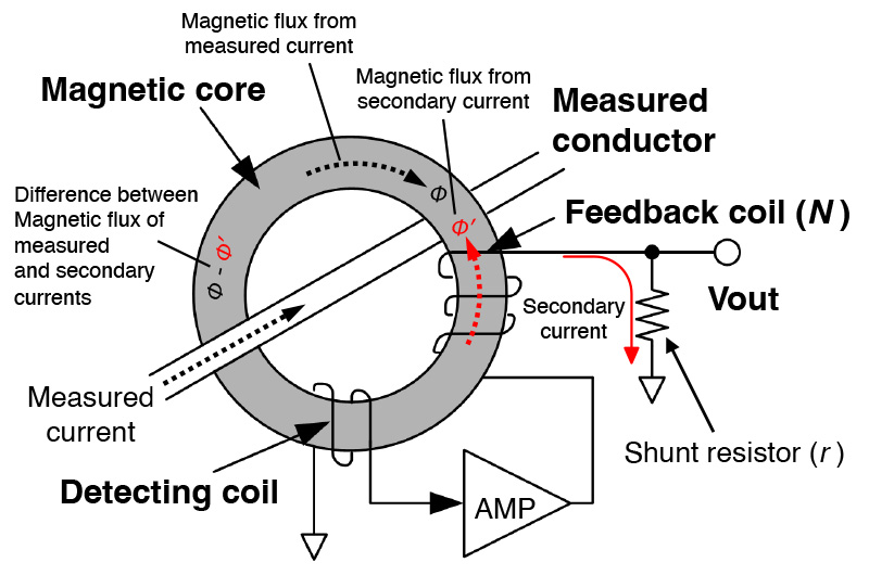
The current sensor of zero flux type (winding detection type) achieves high performance (high accuracy and wide bandwidth) by adding a negative feedback circuit to the basic winding method.
- In the zero-flux method, in order to cancel out the magnetic flux (Φ) produced inside the magnetic core by the AC current flowing in the conductor being measured, a secondary electric current flows to the feedback winding, inducing a secondary magnetic flux (Φ’).
- However, in the low-frequency regions, the magnetic flux (Φ-Φ’) cannot be cancelled and thus remains in the magnetic circuit.
- The detecting coil detects this remaining magnetic flux (Φ-Φ’). Then, a feedback current is added through an amplifier circuit so as to cancel out the magnetic flux (Φ-Φ’) in the low-frequency regions.
- This total secondary electric current flows to the shunt resistor, producing a voltage across the terminals.
- The output voltage is proportional to the electric current flowing in the conductor being measured.
2. Working Principle of Zero flux method: Hall Element Detection (DC/AC)
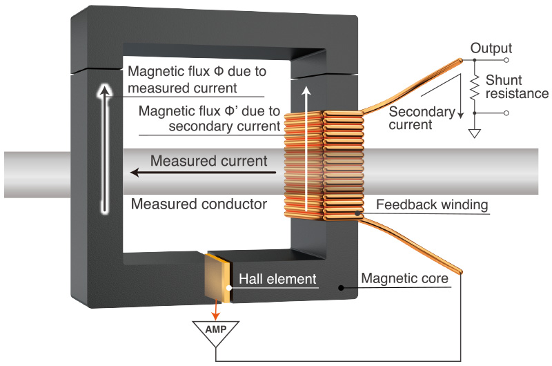
The current sensor of zero flux method (Hall element detection type) achieves high performance (wide bandwidth and low noise) by adding a negative feedback circuit to the basic Hall element method.
- In the zero-flux method, in order to cancel out the magnetic flux (Φ) produced inside the magnetic core by the AC current flowing in the conductor being measured, a secondary electric current flows to the feedback winding, inducing a secondary magnetic flux (Φ’).
- However, in the low-frequency regions, the magnetic flux (Φ-Φ’) cannot be cancelled and thus remains in the magnetic circuit.
- The Hall element detects this remaining magnetic flux (Φ-Φ’). Then, a feedback current is added through an amplifier circuit so as to cancel out the magnetic flux (Φ-Φ’) in the low-frequency regions.
- This total secondary electric current flows to the shunt resistor, producing a voltage across the terminals.
- The output voltage is proportional to the electric current flowing in the conductor being measured.
3. Working Principle of Zero flux method: Fluxgate Detection (DC/AC)
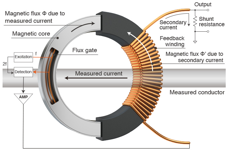
The current sensor of zero flux method (fluxgate detection type) achieves high performance (high accuracy, wide bandwidth, and wide operating temperature range) by combining the fluxgate and the negative feedback circuit.
- In the zero-flux method, in order to cancel out the magnetic flux (Φ) produced inside the magnetic core by the AC current flowing in the conductor being measured, a secondary electric current flows to the feedback winding, inducing a secondary magnetic flux (Φ’).
- However, in the low-frequency regions, the magnetic flux (Φ-Φ’) cannot be cancelled and thus remains in the magnetic circuit.
- The fluxgate detects this remaining magnetic flux (Φ-Φ’). Then, a feedback current is added through an amplifier circuit so as to cancel out the magnetic flux (Φ-Φ’) in the low-frequency regions.
- This total secondary electric current flows to the shunt resistor, producing a voltage across the terminals.
- The output voltage is proportional to the electric current flowing in the conductor being measured.
Features & applications of magnetic balance current sensors
Zero flux method comparison table
| Winding detection (AC) | Hall element detection (DC/AC) | Fluxgate detection (DC/AC) | |
|---|---|---|---|
| Characteristics |
|
|
|
| Application |
|
|
|
| Solutions proposed by HIOKI | CLAMP ON SENSOR 9272-05 |

Related products
HIOKI designs and manufactures our own current sensors and measuring instruments to ensure the best results in power measurement and waveform observation.