DATA LOGGER LR8101, LR8102
Introducing a Modular Data Logger
Engineered for Use in Embedded Applications
Measurement systems are being called upon to deliver sophisticated capabilities as efficient energy use and e-mobility technologies progress.
Hioki data loggers drive solutions that turn measurement system issues into advantages, for example by assuring the safety of high-voltage systems, accommodating enormous numbers of measurement channels, and realizing data compatibility with upstream systems.
Key Features
- Add measurement modules as needed to create the measurement system you need
- [LR8102] Add channels by synchronizing sampling across multiple loggers
- [LR8102] Transfer high-speed data in real time
Ideal Data Loggers for Battery Charge/Discharge Testing
Batteries used in electric vehicles are becoming increasingly high-voltage. To safely measure battery cell voltages and temperatures during charge/discharge testing of high-voltage battery packs, the terminal-to-ground voltage and module-to-module voltage of the instrument are critical.
Hioki's data loggers, LR8101 and LR8102, provide solutions that turn measurement system challenges into advantages. These solutions ensure safety in high-voltage systems, support a large number of measurement channels, and link data with host systems.
Model No. (Order Code)
| LR8101 | Standard model |
|---|---|
| LR8102 | Advanced model |
This product does not include an AC adapter. Either the AC Adapter Z1016, Power Cable L1012, or the AC Power Module M1100 must be purchased separately.
In case of combining with the M7103, the AC Power Module M1100 is required. For data storage, choose either the Hioki SD Memory Card Z4001 (2 GB), SD Memory Card Z4003 (8 GB), or the USB Drive Z4006 (16 GB).
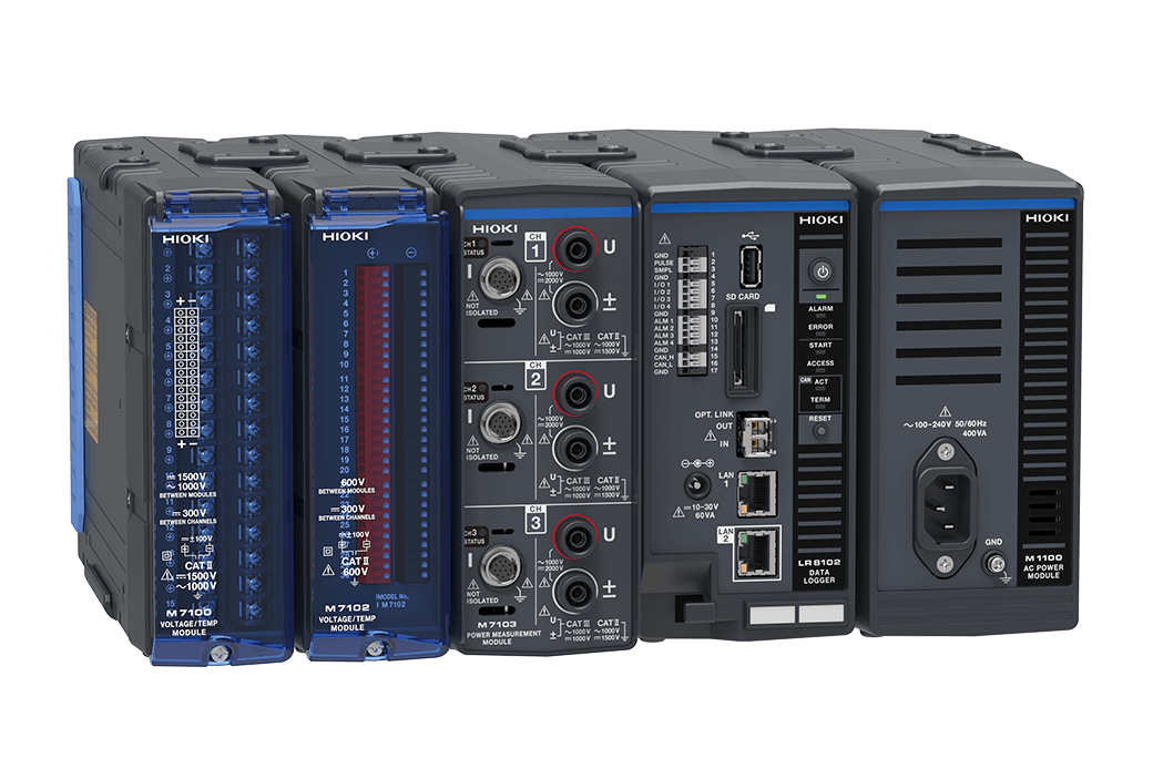
Modular-Based Data Logger System: Versatility and High Accuracy
Offers multi-channel capability, high-voltage rating, all while maintaining the high-accuracy of a power analyzer class instruments
Introducing a revolutionary data logger system, perfect for embedded applications and essential for evaluating energy-efficient products.
Integrating high-precision power and temperature measurements, this system is crucial for comprehensive data on temperature, power consumption, and power conversion efficiency.
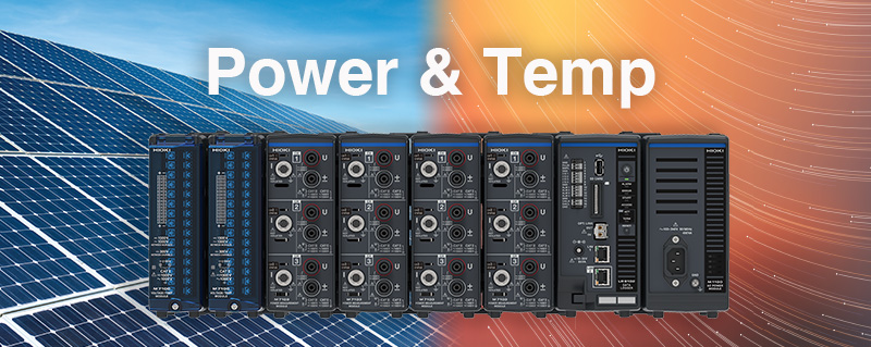
Key Performance Features:
- High Precision: Power analyzer class accuracy for high voltage, high current, and high-power measurements
- Scalability and Versatility: Supports up to 3000 channels for voltage and temperature, and 120 channels for power measurement
- High Speed: Data refresh interval 5 ms
- High-Precision Current Sensors: Measures up to 2000 A
Realizing a Compact, High-precision PV Inverter Testing System
For PV inverter production lines
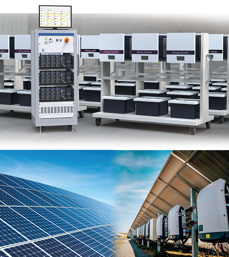
Introducing a modular power meter that’s ideal for PV inverter production line use
Among PV inverters, string inverters are being engineered to operate at higher voltages and to provide more input circuits in order to facilitate energy-efficient operation. Equipment used on lines producing such inverters must support high voltages while providing sufficient expandability to accommodate a growing number of measurement points, all in a smaller testing equipment footprint. Hioki developed the M7103 to satisfy these requirements.
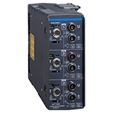
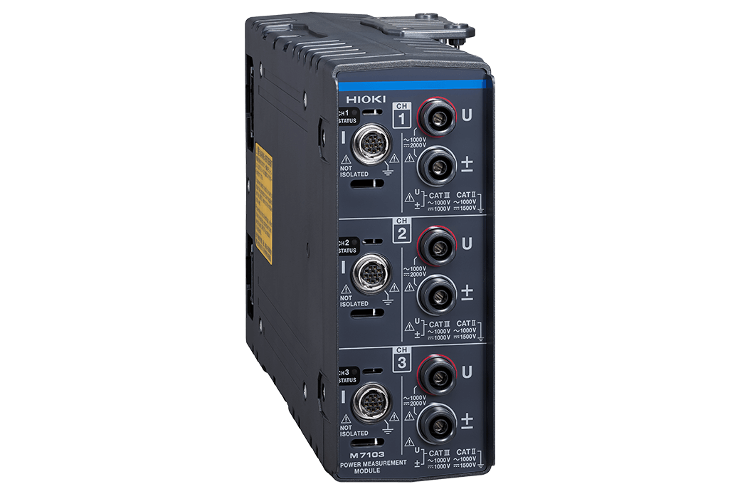
| Module | Power Measurement Module M7103 |
|---|---|
| Max. rated terminal-to-ground voltage | 1000 V DC, 1000 V AC (CAT III) 1500 V DC, 1000 V AC (CAT II) |
| Measurement range | Voltage: 6 V to 1500 V (8 ranges) Current: 40 mA to 2000 A (6 ranges, depends on the current sensor) |
| Number of channels | 3 channels per module |
| Sampling rate | Up to 5 ms |
| External view | 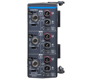 |
| For more product details | In order to use the M7103, the AC Power Module M1100 must be purchased separately. |
Unmatched Capability for Capturing Data from High-Voltage Battery Packs
Suitable for Battery Charge/Discharge Testing
Product Concept
Battery packs consist of many battery cells that are connected in series. Since variability in cell characteristics can lead to a decline in the battery pack’s overall performance, it’s critical to ascertain voltage and temperature behavior at the cell level.
Furthermore, it’s necessary to make a comprehensive evaluation of the battery pack’s overall characteristics during charge/discharge testing. This can be done by measuring individual cells’ voltage and temperature at the same time as total voltage and total current.
Manufacturers are designing batteries of increasingly high voltage for use in electric vehicles (EVs).
As battery voltages rise from 400 V to 800 V, it becomes harder to measure battery cells’ voltage and temperature safely. Instruments used to conduct charge/discharge testing of these high-voltage battery packs must now have higher terminal-to-ground and module-to-module voltage then before.
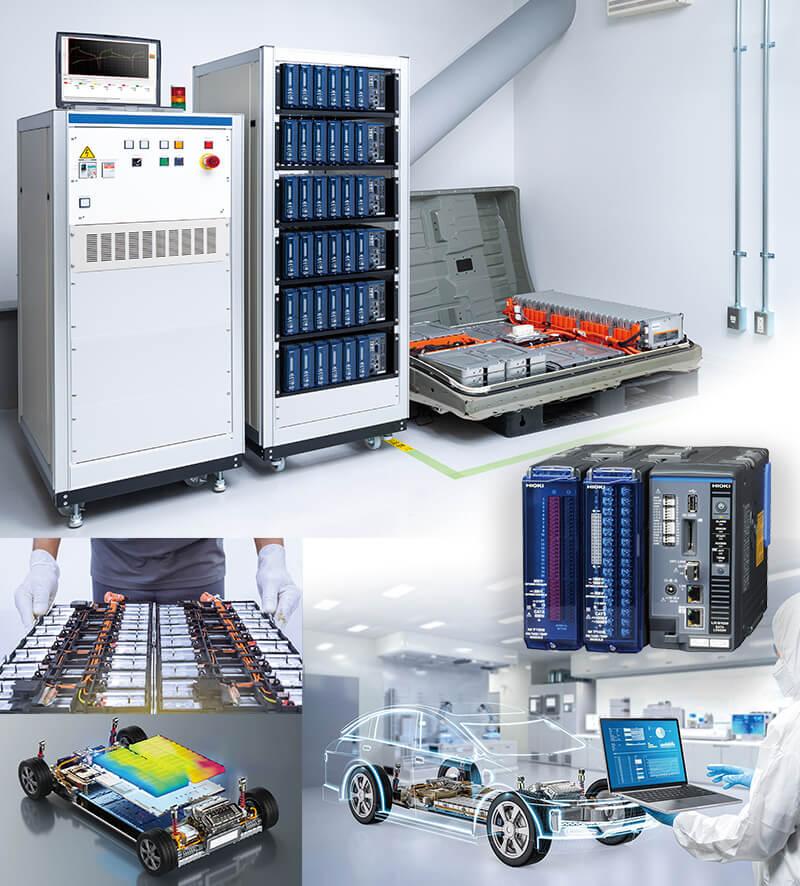
Modules that are ideal for use in measuring the voltage of stack cells in battery packs and in charge/discharge testing on cell production lines
Choose and combine the suitable module for your application.
For measuring the system's total voltage and total current, select the Power Measurement Module M7103.
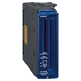
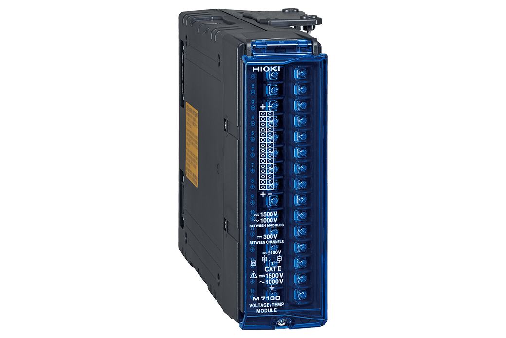
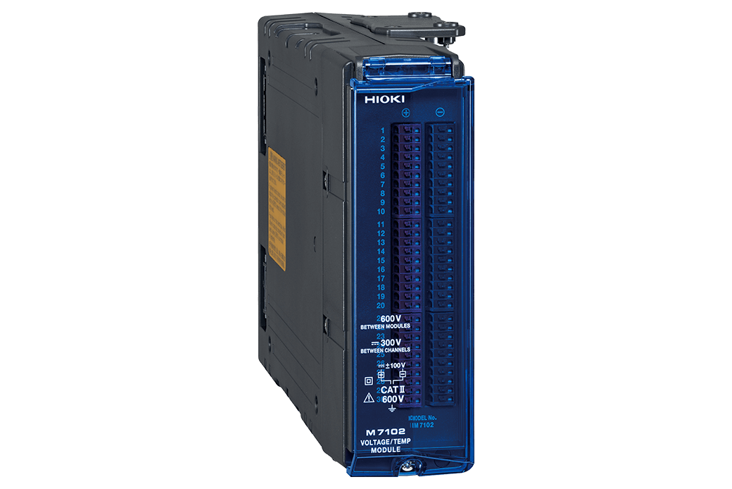
| Module | Voltage/Temp Module M7100 | Voltage/Temp Module M7102 |
|---|---|---|
| Battery packs | For 600 V to 1500 V battery packs | For 600 V or lower battery packs |
| Max. rated terminal-to-ground voltage | 1500 V DC, 1000 V AC (CAT II) | 600 V DC, 600 V AC (CAT II) |
| Max. rated module-to-module voltage | 1500 V DC, 1000 V AC | 600 V DC, 600 V AC |
| Max. number of channels | 15 channels per module | 30 channels per module |
| Sampling rate | Up to 5 ms | Up to 10 ms |
| External view | 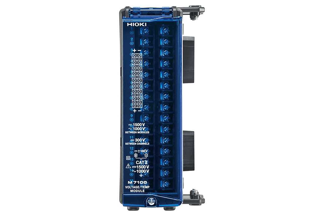 | 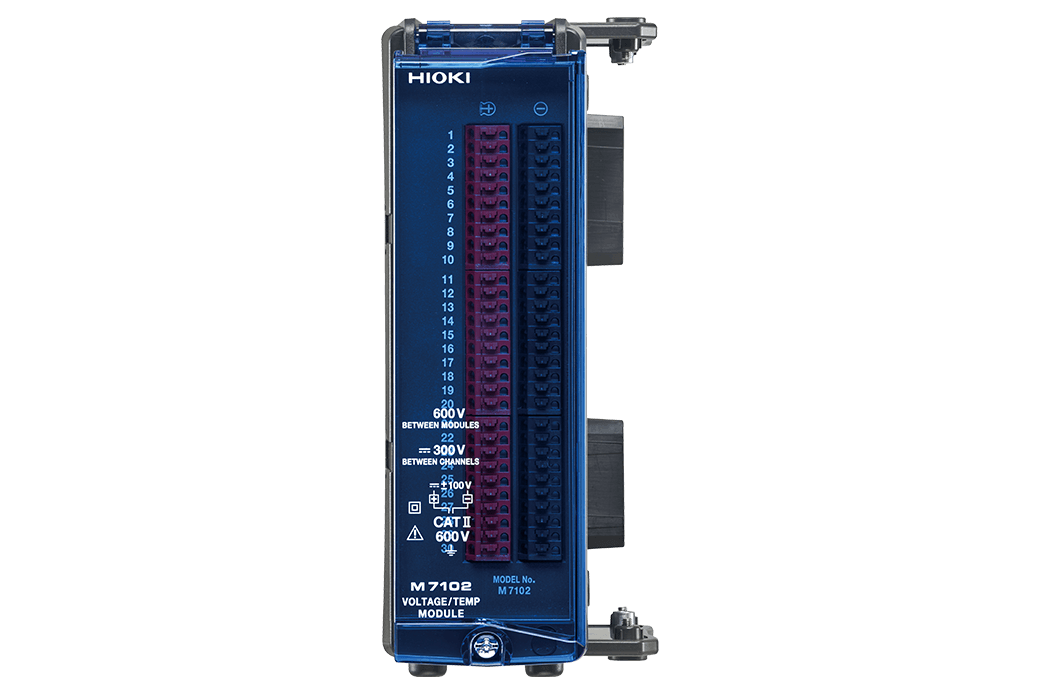 |
| For more product details |
Solutions for charge/discharge testing of batteries
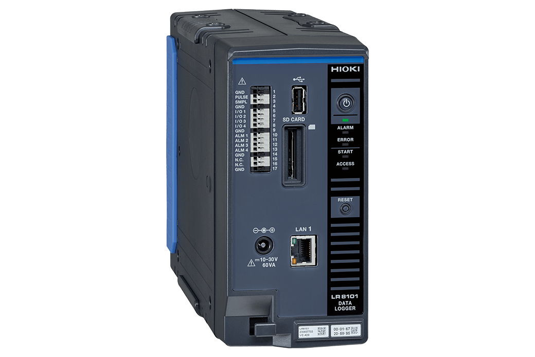
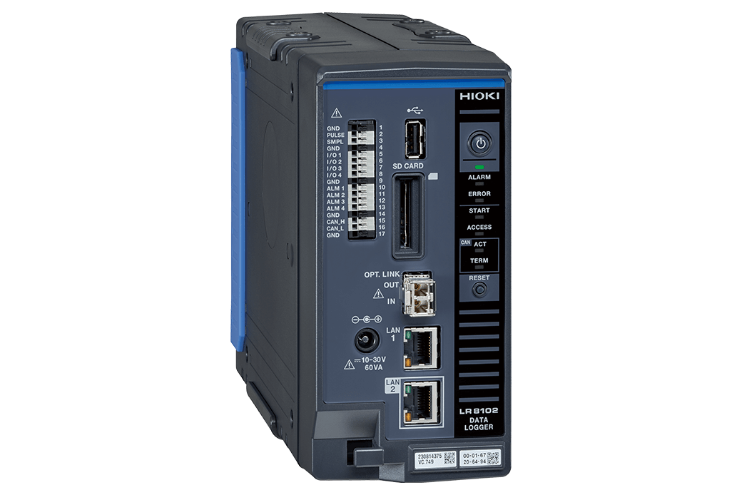
Differences between the LR8101 (Standard model) and LR8102 (Advanced model)
| Functionality | LR8102 Advanced model | LR8101 Standard model |
|---|---|---|
| Connect up to 10 measurement modules | ✓ | ✓ |
| Save data on an SD card or USB drive | ✓ | ✓ |
| Control the instrument and transfer data using communication commands | ✓ | ✓ |
| Data output based on UDP (Transfer high-speed data) (*1) | ✓ | N/A |
| Multiple loggers synchronized for measurement (*2) | ✓ | N/A |
| Data output via CAN (*3) | ✓ | N/A |
| External view | 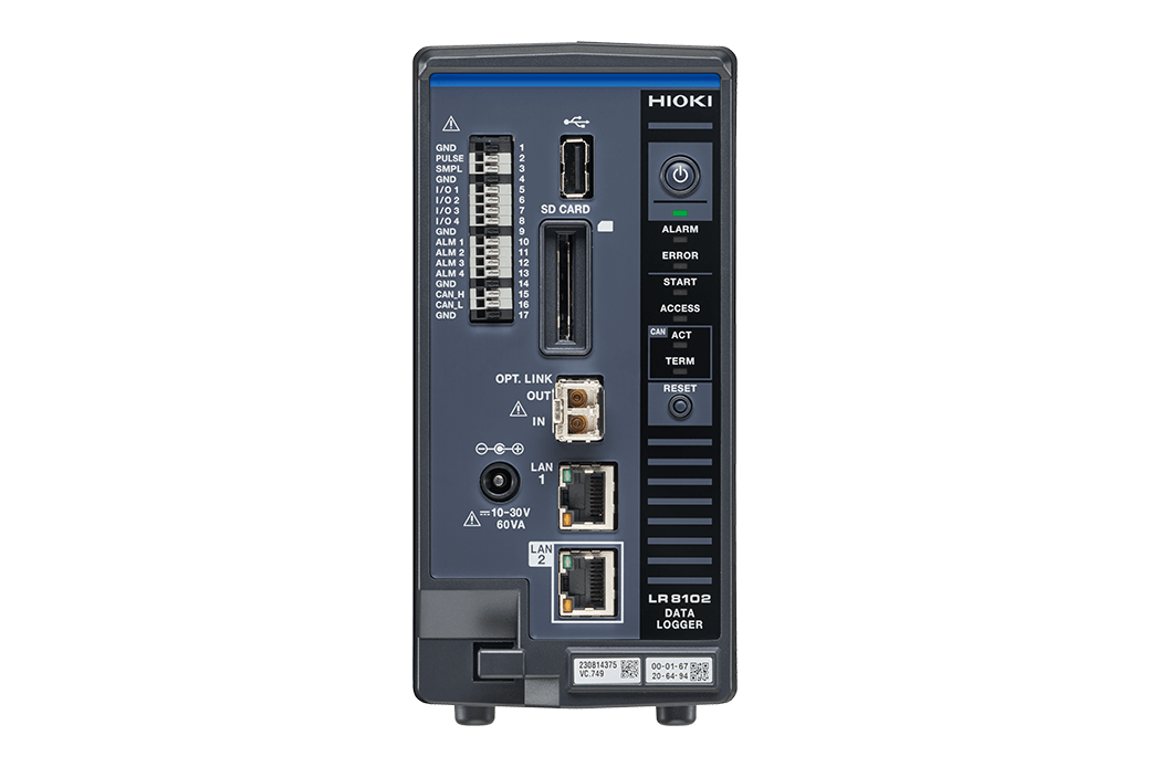 | 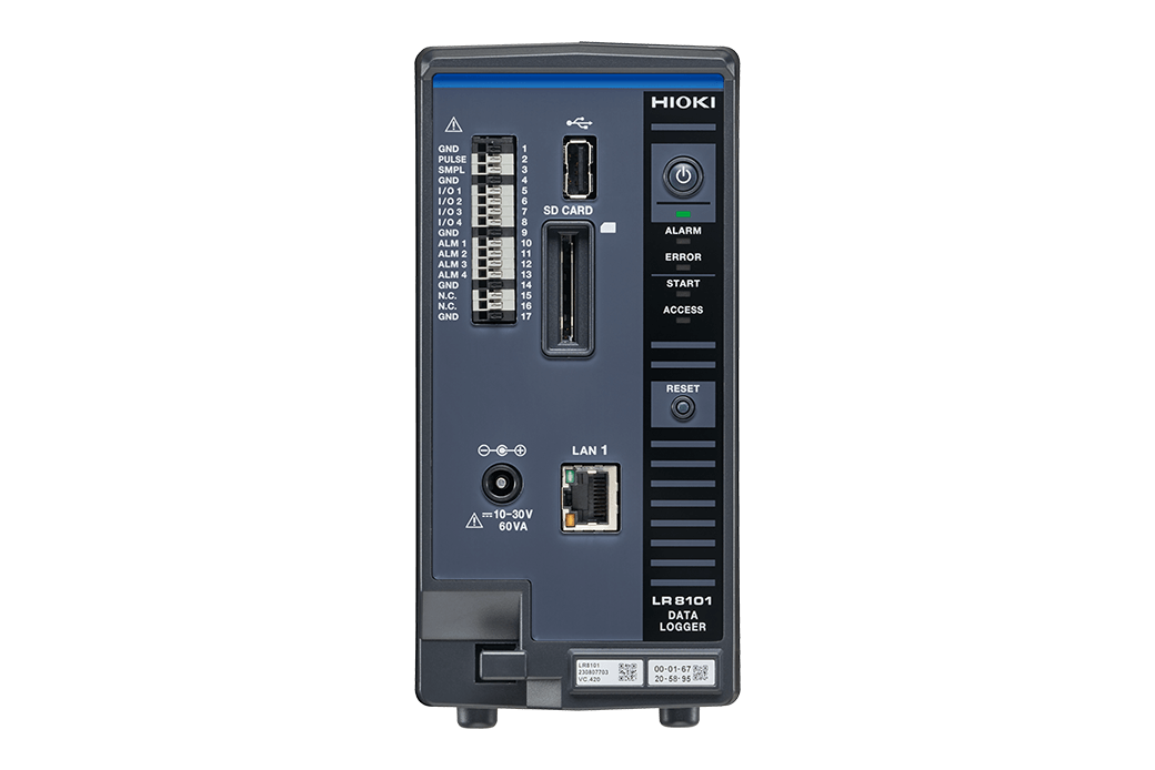 |
- *1: Data output based on UDP
- Measurement data are output for every sampling in real time. The fastest speed is achieved with intervals of 5 ms.
This is useful when realtime processing is required, such as HIL. - *2: Multiple loggers synchronized for measurement
- Synchronized measurement is enabled with an optional Optical Connection Cable L6101 (1 m) or Optical Connection Cable L6102 (10 m).
The measurement data from all of the synchronized instruments can be output from LAN2 of the primary instrument. - *3: Data output via CAN
- The measured value can be output via a Controller Area Network (CAN).
The value can be used for data integration with the information of an in-vehicle device, such as the battery management system (BMS).
General specifications
| Product model | Data Logger LR8102 | Data Logger LR8101 |
|---|---|---|
| Modules that can be connected | See [Options] > [Connectable measurement modules] | |
| Maximum number of module connections | 10 (maximum of 4 units for M7103) | |
| Maximum number of synchronizable loggers | 10 (Requires optical connection cables) |
N/A |
| Power supply | AC adapter: AC Adapter Z1016 (operates on 12 V DC ±10%) External power supply: 10 V DC to 30 V DC AC Power Module M1100: Always required when using the Power Measurement Module M7103. |
|
| Operating temperature and humidity range | −10°C to 50°C (14°F to 122°F), 80% RH or less (non-condensing) | |
| Number of LAN ports | 2 | 1 |
| Communication interface | [LAN1 functionality] Collecting data and setting recording conditions using Logger Utility Setting the initial IP address using Logger Utility Setting and controlling recording using communication commands Manually acquiring data using an FTP Server Automatically sending data via FTP (FTP client) HTTP server function XCP on Ethernet (TCP) NTP client function [LAN2 functionality] XCP on Ethernet (UDP) Measurement data can be output by UDP |
[LAN1 functionality] Collecting data and setting recording conditions using Logger Utility Setting the initial IP address using Logger Utility Setting and controlling recording using communication commands Manually acquiring data using an FTP Server Automatically sending data via FTP (FTP client) HTTP server function XCP on Ethernet (TCP) NTP client function |
| External media | USB Drive, Operation guaranteed: Z4006 (16 GB) SD memory card/SDHC memory card supported, Operation guaranteed: Z4001 (2 GB), Z4003 (8 GB) |
|
| External control terminal | Pulse/logic input (1), External sampling input (1), External input and output (4), Alarm output (4), GND terminal (5), CAN interface (1) | Pulse/logic input (1), External sampling input (1), External input and output (4), Alarm output (4), GND terminal (5) |
| Dimensions and weight | - No module: Approx. 80W × 166H × 238D mm (3.1W × 6.5H × 9.4D in.) (excluding protruding parts), Approx. 1.5 kg (3.3 lbs) - With one M7100 installed: Approx. 134W × 166H × 263D mm (5.3W × 6.5H × 10.4D in.) (excluding protruding parts) - With ten M7100 installed: Approx. 620W × 166H × 263D mm (24.4W × 6.5H × 10.4D in.) (excluding protruding parts) |
|
| Included accessories | Operating Precautions ×1, Startup Guide ×1, Logger Utility, Logger Utility Instruction Manual, CAN Editor, CAN Editor Instruction Manual, Communication Command Instruction Manual) | |
- Note
- This product does not include an AC adapter. Either the AC Adapter Z1016, Power Cable L1012, or the AC Power Module M1100 must be purchased separately. In case of combining with the M7103, the AC Power Module M1100 is required.
- Details
- See the Instruction Manual for more detailed specification information.
Connectable measurement modules (3)
Power supply (3)
This product does not include an AC adapter. Either the AC Adapter Z1016, Power Cable L1012, or the AC Power Module M1100 must be purchased separately. In case of combining with the M7103, the AC Power Module M1100 is required.
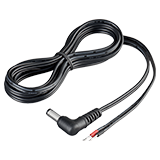
For main unit, DC drive, Connect to external battery, Unprocessed ends, Approx. 2 m (6.6 ft.)
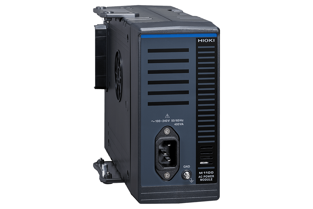
• Supplies power up to four Power Measurement Modules M7103
• 100 V to 240 V AC, 50 Hz/60 Hz
• Approx. 80W × 166H × 238D mm (3.1W × 6.5H × 9.4D in.) (excluding protruding parts), approx. 2.0 kg (4.4 lbs)
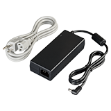
100 V to 240 V AC
Synchronizing multiple loggers, CAN output [both only for the LR8102] (3)
- Synchronizing sampling across multiple loggers (optical connection): Use when synchronizing measurements across multiple Data Logger LR8102 instruments. One optical connection cable is required for each logger.
- CAN connectivity: Use to combine data with information about onboard devices such as a battery management system (BMS). One CAN cable is required for each logger.
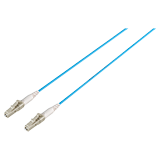
1 m (3.3 ft.)

10 m (32.8 ft.)
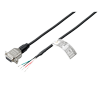
Unprocessed on one end, 1.8 m (5.9 ft.)
Storage media (3)
Precaution: Be sure to use storage media supplied by Hioki. Instruments may not be able to write to or read from storage media other than Hioki media; proper operation not guaranteed.
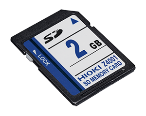
2 GB capacity
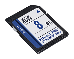
8 GB capacity
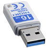
16 GB, long-life, high-reliability SLC flash memory
For Measuring and Analyzing (3)
The Logger Utility and Can Editor are included accessories.
Connect the computer to the logger (LAN1 port).
- A hub and one LAN cable to each logger are needed in order to simultaneously configure multiple devices.
(The LAN1 port for is used for configuring the instrument's settings, even when using UDP output.
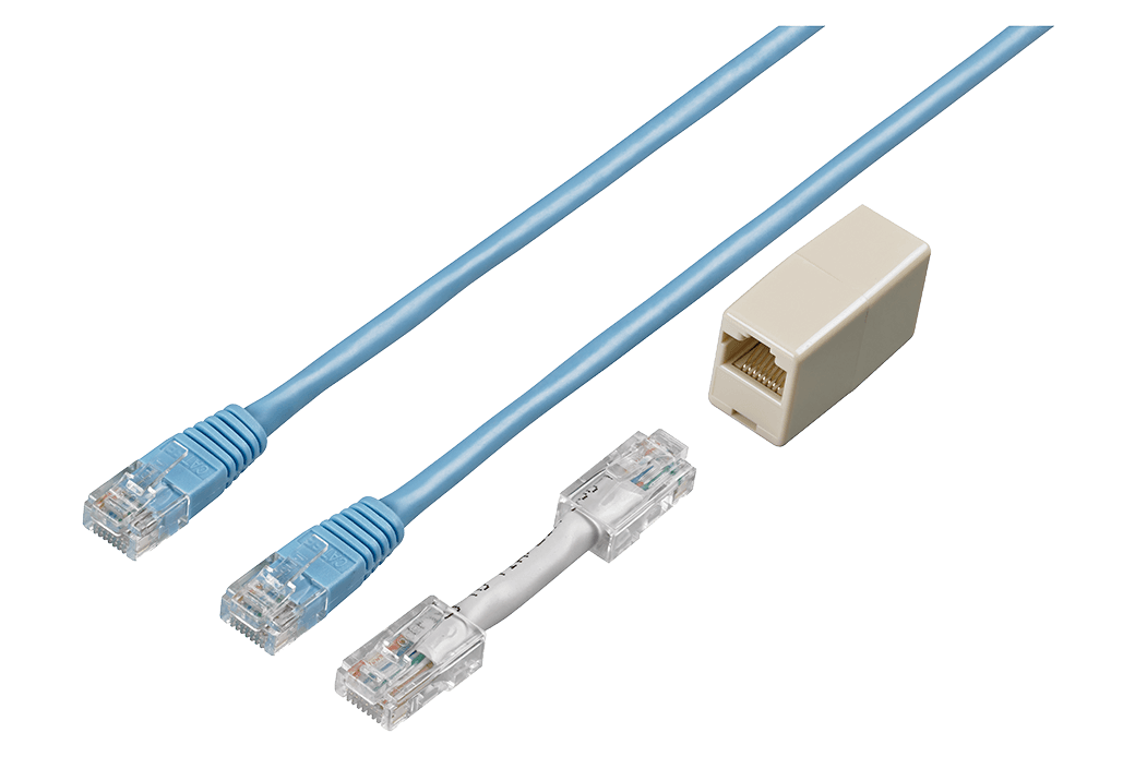
Straight Ethernet cable, supplied with straight-to-cross conversion adapter, 5 m (16.4 ft.)
- Next-Generation Data Logger Ideal for EV Energy & Thermal Management
- Supporting the Future of Energy Conversion! Revolutionizing Thermal Management with High-Precision Simultaneous Power and Temperature Measurement
- Highly stable evaluation of multi-MPPT inverter conversion efficiency
- A data logger that can interoperate with an HIL simulation system thanks to high-speed, real-time data output
- Charge/Discharge Testing of High-Voltage Batteries

