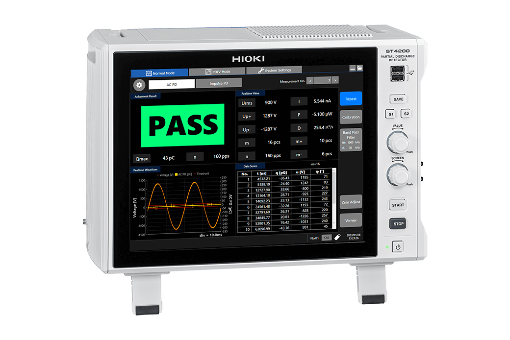
PARTIAL DISCHARGE DETECTOR ST4200
Dual partial-discharge detector with high noise resistance for EV motors
Why is partial discharge testing of motor windings necessary?
Deep inside the motor winding a tiny discharge appears, unseen but real. Each surge pulse fuels the damage, eroding the insulation from within. Cracks, carbonization…what begins as a faint spark can end in breakdown — or fire.
Insulation resistance and hipot tests? They find what’s already failed. Partial discharge starts long before silent, cumulative, irreversible.
Partial discharge testing reveals what others can’t see early degradation, hidden defects, the beginning of failure. Reliability starts before the fault.
The Hioki ST4200-50 delivers stable, reproducible measurements even in noisy production lines. Detect. Protect. Trust. Hioki — visualizing the hidden destruction.
Noise-Resistant PD Testing for Enhanced Motor Quality
The ST4200-50 Partial Discharge Detector offers comprehensive partial discharge (PD) detection. It also enables seamless system integration for motor production testing when paired with the SW2001 High Voltage Multiplexer. Furthermore, the ST4200-50's PD detection uses high-frequency CTs which mitigate noise interference common to production lines. Such noise on production lines make PD detection using a microwave antenna often difficult, and at times, nearly impossible.
Key Features
- Compatible with the SW2001 High Voltage Multiplexer
- Noise-resistance through high-frequency CT
- AC and Surge dual-mode partial discharge detection
Model No. (Order Code)
| ST4200-50 | |
|---|---|
| AC Partial Discharge Test Kit | ST4200-50, ST9210, 3153, L2270, L2271, L2265, L2266, L9218 (x2), L9637 |
| Surge Partial Discharge Test Kit | ST4200-50, ST4030A, surge PD sensor set |
| AC/Surge Partial Discharge Test Kit | ST4200-50, ST9210, ST4030A, 3153, L2270, L2271, L2265, L2266, L9218 (x2), L9637, surge PD sensor set |
Maximize the detection of latent failures
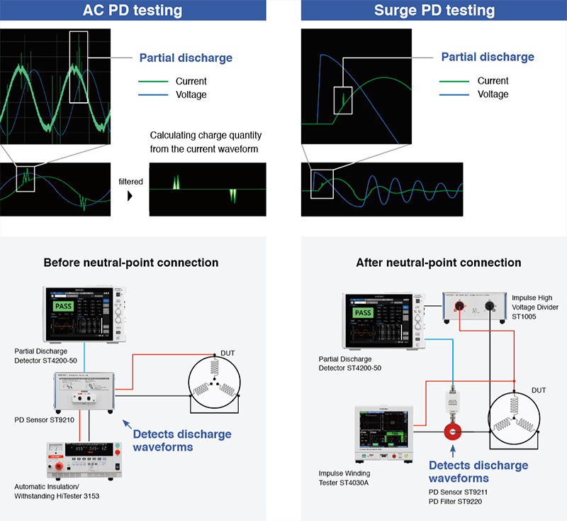
Dual-mode PD detection
Discover latent insulation defects in motor windings with the AC PD test (IEC 60270 and IEC 60034-27-1 compliant) and surge PD test (IEC 61934 Ed. 2 and IEC60034-27-5 compliant). The ability to select between the two types of PD tests allows you to customize your inspection process to the specific needs of each motor, maximizing the detection of latent failures.
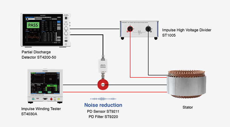
Reliable PD testing even on the production line
Noise-resistant PD detection with a high-frequency CT
Partial discharge testing on production lines with a microwave antenna is highly susceptible to noise interference. Using a high-frequency CT minimizes noise, simplifies installation by reducing the need for precise positioning, and thus prevents measurement errors.
Simplified system design for reduced noise impact
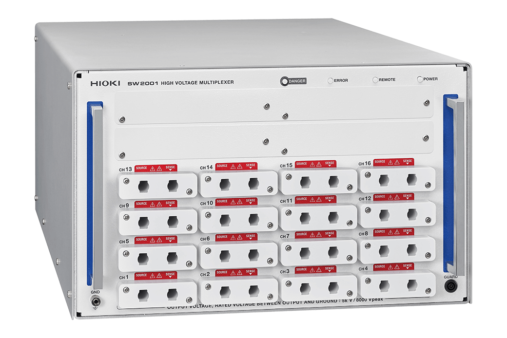
Integration with the SW2001 High Voltage Multiplexer
Complex testing environments often come with high noise which are difficult to reduce. The ST4200-50 Partial Discharge Detector's high noise resistance can be further minimized by integrating with the SW2001's multiplexer-based architecture. This design significantly reduces wiring complexity by consolidating multiple input signals, minimizing cable runs and interconnections. This approach effectively reduces potential noise sources such as electromagnetic interference (EMI), ground loops, and capacitive coupling, resulting in more accurate and reliable measurements.
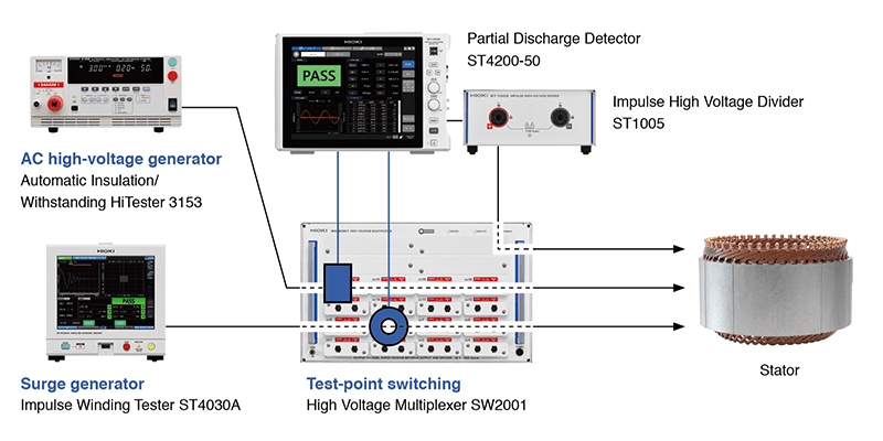
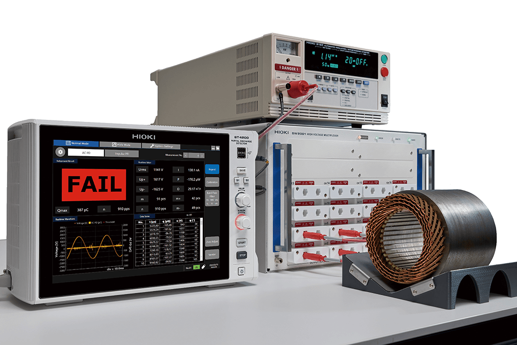
Basic setup for partial discharge testing:
- 1. Partial Discharge Detector ST4200-50
- 2. Automatic Insulation/Withstanding HiTester 3153 as an AC high-voltage power supply
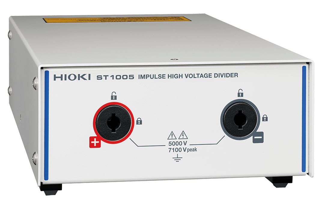
- 3. Impulse Winding Tester ST4030A as an Impulse power supply
- 4. High Voltage Multiplexer SW2001 for switching between test points
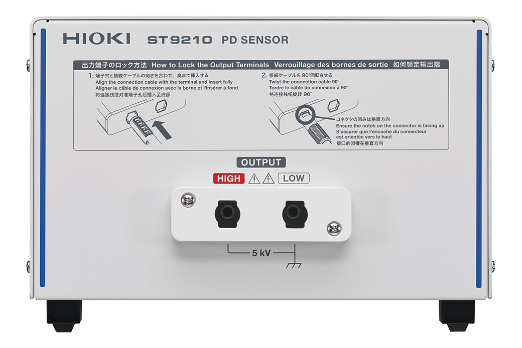
- 5. Partial discharge sensor for AC PD testing *1
- 6. Partial discharge sensor for surge PD testing *1
- *1:These sensors are built into the SW2001. Please specify at time of order as the component is embedded during the manufacturing process.
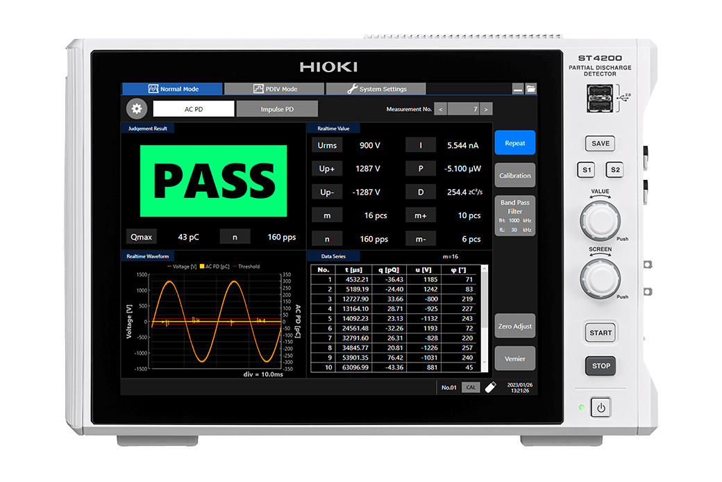
AC PD measurement
| Detection method | Discharge measurement method using detection impedance and band pass filter. Conforms to the detection method in IEC 60270. |
|---|---|
| Test frequency range (applied voltage) |
45 Hz to 1.1 kHz |
| Charge quantity measurement range | 10 pC ≤ Q ≤ 500 pC (test piece capacitance C: 200 pF ≤ C < 2 nF) 10 pC ≤ Q ≤ 2500 pC (test piece capacitance C: 2 nF ≤ C ≤ 10 nF) |
| Measurement parameters | [Normal mode] Maximum repeating PD strength (Q max), PD pulse count (m, m+, m-), PD pulse incidence (n), voltage RMS value (U rms), voltage crest value (Up+, Up-), voltage peak-to-peak (Upp), average discharge current (I), discharge power (P), second-order rate (D), PD pulse apparent charge (q), PD pulse phase angle (φ) [PDIV mode] (normal mode parameters plus the following) PD inception voltage (Ui), PD extinction voltage (Ue) |
Impulse PD (surge PD) measurement
| Detection method | Discharge current detection using CT and digital filters Conforms to the detection method in IEC 61934 Edition 2.0. |
|---|---|
| Sampling rate | 200 MS/s |
| Measurement parameters | [Normal mode] PD peak discharge magnitude (Qpk), pulse sequence PD count (m) [PDIV mode] (normal mode parameters plus the following) PD inception voltage (PDIV), repetitive PD inception voltage (RPDIV), repetitive PD extinction voltage (RPDEV), PD extinction voltage (PDEV), repeating PD peak discharge magnitude (RQpk) |
High-voltage source control
| Control description | Cooperative control of withstanding voltage tester and impulse winding tester used as high-voltage generators for partial discharge testing |
|---|---|
| Compatible instruments (as of Feb. 2025) | Automatic Insulation/Withstanding HiTester 3153, Impulse Winding Tester ST4030A, etc |
Specifications shared by AC PD and impulse PD (surge PD) measurement
| Functions | Graph display function, judgment function |
|---|---|
| Save destination | SD memory card, USB drive, SSD (Use only storage media sold by Hioki.) |
| Effects of radiative radio frequency electromagnetic fields | 50 pC or less (at 10 V/m) |
| Effects of conductive radio frequency electromagnetic fields | 50 pC or less (at 10 V) |
| Effects of pulse noise superposed on power supply | 50 pC or less (with pulse noise of 1 kV and pulse width of 50 ns) |
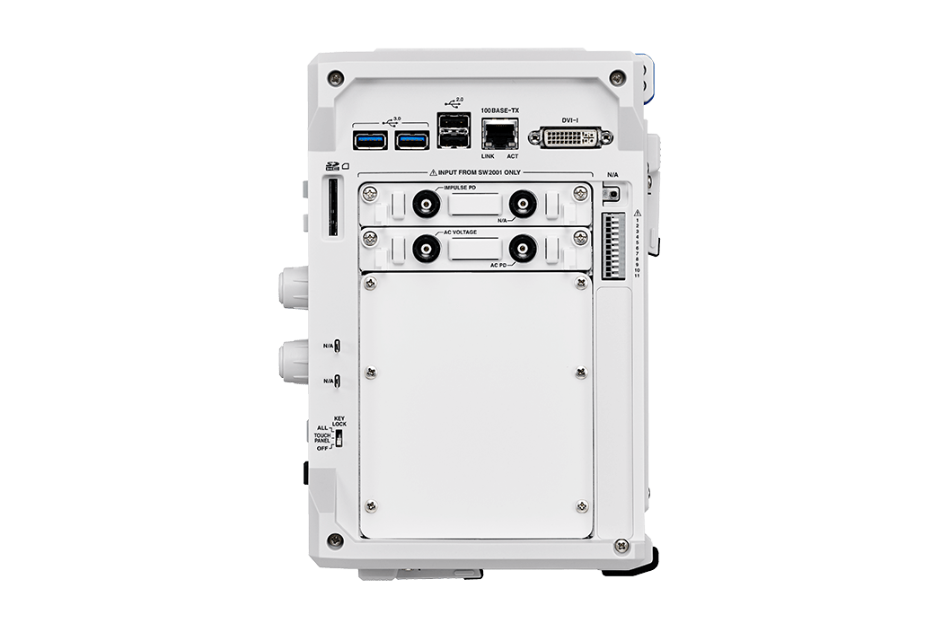
| Interfaces | LAN, USB, RS-232C* (please use a commercially available USB-serial conversion cable.), EXT. I/O (measurement start, measurement cancel, overall judgment PASS, overall judgment FAIL) *For connecting to secondary instruments (e.g., Automatic Insulation/Withstanding HiTester 3153) |
| Power supply | Rated supply voltage: 100 to 240 V AC; rated power: 300 VA |
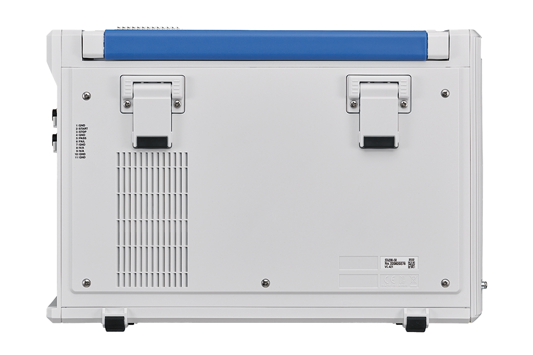
| External dimensions | Approx. 353 mm (13.9 in.) W × 235 mm (9.25 in.) H × 154.8 mm (6.09 in.) D (excluding protruding parts) |
| Mass | Approx. 7.3 kg (257.5 oz.) (with U8332); approx. 7.1 kg (250.4 oz.) (without U8332) |
| Included accessories | Power cord × 1, operating precautions × 1, startup guide × 1 |
Multiplexer (1)
Multiplexer (specify built-in PD sensor ST9200 and/or ST9201-50 (Available soon) at time of order)
External storage media (3)
Precaution:
Use only storage media sold by Hioki. Compatibility and performance are not guaranteed for storage media made by other manufacturers. You may be unable to read from or save data to such media.
2 GB capacity
8 GB capacity
16 GB, long-life, high-reliability SLC flash memory
Internal storage media (1)
Please specify at time of order as one of these components are embedded during the manufacturing process.
Must be specified at time of order; internal drive, 256 GB
Communication cable (2)
The L9637 should be used with a commercially available USB-serial converter to connect the ST4200 to secondary instruments.
1 m
• For external control
• Double shielding
• 9-pin/9-pin, Cord length 3 m (9.8 ft.)
Partial discharge sensor (3)
Necessary when not used with the SW2001.
For surge partial discharge detection
For surge partial discharge test
-
PARTIAL DISCHARGE DETECTOR ST4200-50, HIGH VOLTAGE MULTIPLEXER SW2001-04, SW2001-08, SW2001-16
 Startup Guide
Simplified Chinese
Ver.01
Startup Guide
Simplified Chinese
Ver.01
-
PARTIAL DISCHARGE DETECTOR ST4200-50
Instruction Manual
Simplified Chinese
Ver.01
-
PARTIAL DISCHARGE DETECTOR ST4200-50, HIGH VOLTAGE MULTIPLEXER SW2001-04, SW2001-08, SW2001-16
Startup Guide
English
Ver.01
-
PARTIAL DISCHARGE DETECTOR ST4200-50
Instruction Manual
English
Ver.01