Tantalum capacitors
What are tantalum capacitors?
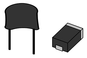
Tantalum capacitors are a type of electrolytic capacitor that uses the metal tantalum for the anode. They provide higher capacitance in a smaller package than other types of capacitors, and they offer better voltage and temperature characteristics than high-capacitance ceramic capacitors.
Setting example of measurement conditions
| Parameters | Cs-D (120Hz), Rs(100kHz) | |||||||||||||||||||||
| Frequency | 120Hz, 100kHz | |||||||||||||||||||||
| DC bias | OFF | |||||||||||||||||||||
| Signal level | 0.5Vrms | |||||||||||||||||||||
| Measurement range | AUTO | |||||||||||||||||||||
| Speed | SLOW2 | |||||||||||||||||||||
| LowZ mode | ON | |||||||||||||||||||||
* Otherwise, default settings are used.
* The above settings apply to an example measurement. Since optimal conditions vary with the measurement target, specific settings should be determined by the instrument operator.
Surface mount fixed tantalum electrolytic capacitors with manganese dioxide solid electrolyte (IEC 60384-3) (JIS C5101-3)
| Parameters | Rated capacitance | Rated voltage | Measurement frequency | Measurement voltage*1 | DC bias *2 | |||||||||||||||||||||||||
| C,D(tanδ) | All | All | 100Hz or 120Hz | 0.5Vrms or less | 0.7V to 1.0V | |||||||||||||||||||||||||
| Rs(ESR), Z | All | All | 100kHz | 0.5Vrms or less | 0.7V to 1.0V | |||||||||||||||||||||||||
Fixed tantalum capacitors with non-solid electrolyte and foil electrode(IEC 60384-15)(JIS C5101-15)
| Parameters | Rated voltage Rated capacitance | Measurement frequency | Measurement voltage*1 | DC bias *2 | ||||||||||||||||||||||||||
| C,D(tanδ) | All | 100Hz or 120Hz | 0.1Vp to 1.0Vp | 2.1V to 2.5V *3 | ||||||||||||||||||||||||||
| Rs(ESR) Z | All | Choose the frequency that yields the lowest impedance value from the following: 100 Hz, 120 Hz, 1 kHz, 10 kHz, 100 kHz, 1 MHz. | 0.1Vp to 1.0Vp | 2.1V to 2.5V *4 | ||||||||||||||||||||||||||
Surface mount fixed tantalum electrolytic capacitors with conductive polymer solid electrolyte(IEC 60384-24)(JIS C5101-24)
| Parameters | Rated capacitance | Rated voltage | Measurement frequency | Measurement voltage*1 | DC bias *2 | |||||||||||||||||||||||||
| C,D(tanδ) | All | 2.5V or less | 100Hz or 120Hz | 0.5Vrms or less | 1.1V to 1.5V | |||||||||||||||||||||||||
| 2.5V or greater | 1.5V to 2.0V | |||||||||||||||||||||||||||||
| Rs(ESR),Z | All | All | 100kHz | 0.5Vrms or less | OFF | |||||||||||||||||||||||||
*1 The measurement voltage (i.e., the voltage applied to the sample) is the voltage obtained by dividing the open-terminal voltage by the output resistance and the sample.
*1 The measurement voltage (i.e., the voltage applied to the sample) can be calculated based on the open-terminal voltage, the output resistance, and the sample’s impedance.
*2 DC bias need not be applied
*3 DC bias need not be applied to bipolar capacitors.
*4 Apply only when using a measurement voltage of 0.5 Vp or greater.
Determining Cs and Cp
Generally speaking, series equivalent circuit mode is used when measuring low-impedance elements (approximately 100Ω or less) such as high-capacitance capacitors, and parallel equivalent circuit mode is used when measuring high-impedance elements (approximately 10 kΩ or greater) such as low-capacitance capacitors. When the appropriate equivalent circuit mode is unclear, for example when measuring a sample with an impedance from approximately 100Ω to 10 kΩ, check with the component’s manufacturer.
Instruments for Mass Production Applications
| Model | Measurement frequency | Features | ||||||||||||||||||||||||||||
| IM3523 | DC, 40Hz to 200kHz | Measurement time: 2ms, high cost performance | ||||||||||||||||||||||||||||
| IM3533 | DC, 1mHz to 200kHz | Internal DC bias function, touch panel | ||||||||||||||||||||||||||||
*For more information, please see the product catalog.
Instruments for Research & Development Applications
| Model | Measurement frequency | Features | ||||||||||||||||||||||||||||
| IM3570 IM9000 | DC, 4Hz to 5MHz | Frequency sweep with analyzer mode | ||||||||||||||||||||||||||||
| IM3570 | ||||||||||||||||||||||||||||||
| IM3590 | DC, 1mHz to 200kHz | Can measure ESR and ESL separately with its equivalent circuit analysis function. | ||||||||||||||||||||||||||||
*For more information, please see the product catalog.
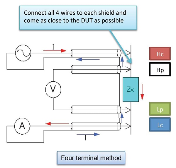
Four-terminal method
When shielding is connected close to the sample Zx, the measurement current I will return via the shielding. Because the magnetic flux generated by the current returning through the shielding negates the magnetic flux generated by the measurement current I, this technique is especially useful as a way to reduce measurement error during low-impedance measurement (Models IM35xx).
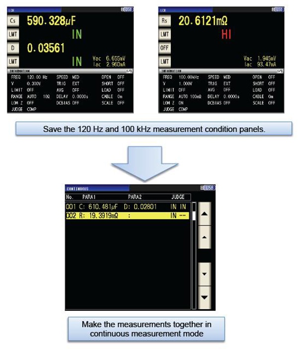
Continuous measurement mode
The IM35xx series’ continuous measurement mode can be used to make continuous measurements while varying settings (frequency and level). In the example on the right, continuous Cs-D (120 Hz) and ESR (100 kHz) measurements are performed.