Electrolytic capacitors
How are electrolytic capacitors measured?
The measurement conditions used to define an electrolytic capacitor’s capacitance are set forth in IEC standards, and the nominal values cited by capacitor manufacturers are measured values obtained in accordance with those standards. However, because the capacitance values of electrolytic capacitors vary greatly with the measurement frequency, capacitance values should be checked at the frequency at which the circuit in question will actually be used.
Measure the equivalent series resistance (ESR), which includes factors such as the resistance of the electrolytic capacitor’s internal electrodes and the electrolyte resistance, and the tangent D (tanδ) of the loss angle under the same conditions as the capacitance.
Setting example of measurement conditions
| Parameters | Cs-D-Rs | |||||||||||||||||||||
| Frequency | 120Hz, frequency at which circuit will actually be used | |||||||||||||||||||||
| DC bias | ON 1.0V | |||||||||||||||||||||
| Signal level | 0.5Vrms | |||||||||||||||||||||
| Measurement range | AUTO | |||||||||||||||||||||
| Speed | SLOW2 | |||||||||||||||||||||
| LowZ mode | ON | |||||||||||||||||||||
*The above settings apply to an example measurement. Since optimal conditions vary with the measurement target, specific settings should be determined by the instrument operator.
| Parameters | Rated capacitance | Rated voltage | Measurement frequency | Measurement voltage*1 | DC bias *2 | |||||||||||||||||||||||||
| C,D(tanδ) Rs(ESR) | All | All | 100Hz or 120Hz | 0.5Vrms | 0.7 to 1.0V | |||||||||||||||||||||||||
*1 The measurement voltage (i.e., the voltage applied to the sample) is the voltage obtained by dividing the open-terminal voltage by the output resistance and the sample.
*1 The measurement voltage (i.e., the voltage applied to the sample) can be calculated based on the open-terminal voltage, the output resistance, and the sample’s impedance.
*2 DC bias need not be applied.
Low impedance high accuracy mode settings
In low impedance high accuracy mode, the instrument’s output resistance is reduced, and the measurement current is applied repeatedly for increased measurement precision. When measuring a capacitor with a high capacitance of greater than 100μF (and therefore low impedance), low-impedance high-precision mode yields more stable measurement. The graph below compares repeatability when using the IM3570 to make measurements with low-impedance high-precision mode enabled and disabled (100kHz, 1Ω range, 1V).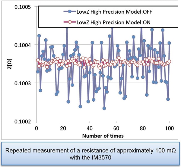
*The conditions under which low-impedance high-precision mode can be enabled vary with the instrument model. Please refer to the instruction manual of the instrument you are using.
Instruments for Mass Production Applications
| Model | Measurement frequency | Features | ||||||||||||||||||||||||||||
| IM3523 | DC, 40Hz to 200kHz | Measurement time: 2ms, high cost performance | ||||||||||||||||||||||||||||
| IM3533 | DC, 1mHz to 200kHz | Internal DC bias function, touch panel | ||||||||||||||||||||||||||||
Instruments for Research & Development Applications
| Model | Measurement frequency | Features | ||||||||||||||||||||||||||||
| IM3570 IM9000 | DC, 4Hz to 5MHz | Frequency sweep with analyzer mode | ||||||||||||||||||||||||||||
| Optional equivalent cuircuit analysis firmware for the IM3570 | ||||||||||||||||||||||||||||||
| IM3590 | DC, 1mHz to 200kHz | Can measure ESR and ESL separately with its equivalent circuit analysis function. | ||||||||||||||||||||||||||||
Equivalent series resistance (ESR) and loss coefficient D (tanδ): Circuit
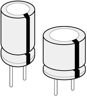
The figure on the right illustrates a standard equivalent circuit for an electrolytic capacitor.
At low frequencies (50 Hz to 1 kHz), the reactance (XL) resulting from the equivalent series inductance L is extremely small and can be considered to be zero.
C: Capacitance
r: Equivalent series resistance of anodic oxidation coatings
R: Equivalent series resistance (ESR)
L: Equivalent series inductance
*General description of Aluminum Electrolytic Capacitors (NICHICON CORPORATION)

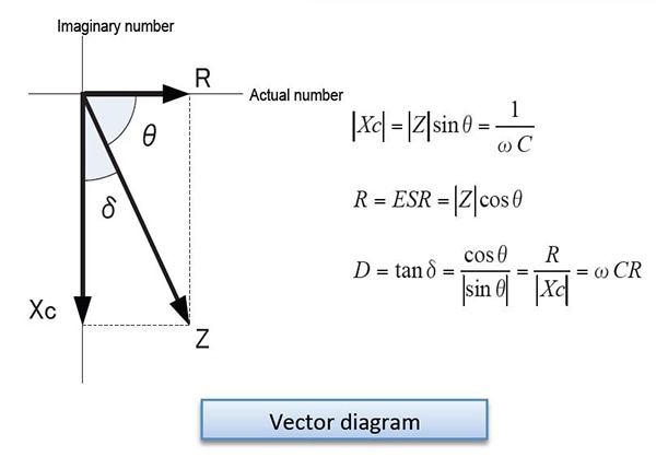
Equivalent series resistance (ESR) and loss coefficient D (tanδ): Vector relationship
The resistance and reactance components of each element at this time are characterized by the vector relationship shown in the figure on a complex plane.
An ideal capacitor would have R = 0 and a loss coefficient D = 0, but since actual capacitors have various resistance components, including electrode foil resistance, electrolyte resistance, and contact resistance of leads and other parts, the equivalent series resistance ESR and loss coefficient D (tanδ) serve as useful indicators for use in evaluating electrolytic capacitor quality.
Equivalent series resistance (ESR) and loss coefficient D (tanδ): Evaluation
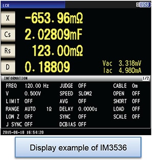
>Since the IM3533 and IM3536 can simultaneously measure and display four parameters, they can be used to simultaneously check the reactance X, capacitance C, equivalent series resistance Rs, and loss coefficient D as indicators for use in evaluating electrolytic capacitors, as shown in the example screenshot on the right.
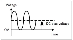
DC bias measurement function
Electrolytic capacitors generally are available in polarized and bipolar variants. A DC bias voltage must be applied to polarized capacitors as necessary to prevent application of a reverse voltage.
Since the IM3533 and IM3536 provide a built-in DC bias voltage function, they can apply a DC bias to capacitors, eliminating the need for an external DC power supply.
Determining Cs and Cp
Generally speaking, series equivalent circuit mode is used when measuring low-impedance elements (approximately 100Ω or less) such as high-capacitance capacitors, and parallel equivalent circuit mode is used when measuring high-impedance elements (approximately 10 kΩ or greater) such as low-capacitance capacitors. When the appropriate equivalent circuit mode is unclear, for example when measuring a sample with an impedance from approximately 100Ω to 10 kΩ, check with the component’s manufacturer.