How to Use an Impedance Meter
Learn how to use an impedance meter! Basic measurement methods
Overview
Impedance meters measure impedance, or resistance to the flow of an alternating current (AC). This page provides a detailed introduction to basic knowledge about impedance, methods for measuring impedance, and how to use an impedance meter.
What is impedance?
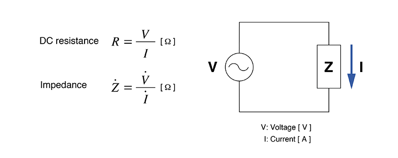
Let's start by defining impedance. In a word, impedance is a quantity that expresses resistance to the flow of an AC current.
When you connect an electric product, motor, or other device to an AC power source, current will flow through the device’s circuitry. Impedance is calculated by dividing the voltage in such a circuit by its current. In short, impedance can be described as limiting the flow of current in an AC circuit. Impedance is indicated by the symbol “Z” and measured in ohms (Ω), the same unit used to measure DC resistance. The higher the impedance, the more resistance there is to the flow of current.
How is impedance measured?
Since impedance itself is not a visible phenomenon, it’s necessary to use a measuring instrument in order to measure it. Instruments capable of measuring impedance include impedance meters, LCR meters, and impedance analyzers. There are a number of methods by which impedance can be measured.
Bridge method
This method uses a bridge circuit to calculate an unknown resistance. It requires that balance adjustment be performed using a galvanometer. Although the technique provides a high degree of accuracy (about 0.1%), it’s poorly suited to high-speed measurement.
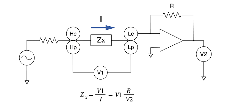
I-V method
This method calculates impedance by measuring the voltages across a current detection resistor and an unknown impedance. It can also be used to measure samples that are grounded. As the impedance rises, the technique becomes increasingly susceptible to the effects of the voltmeter.
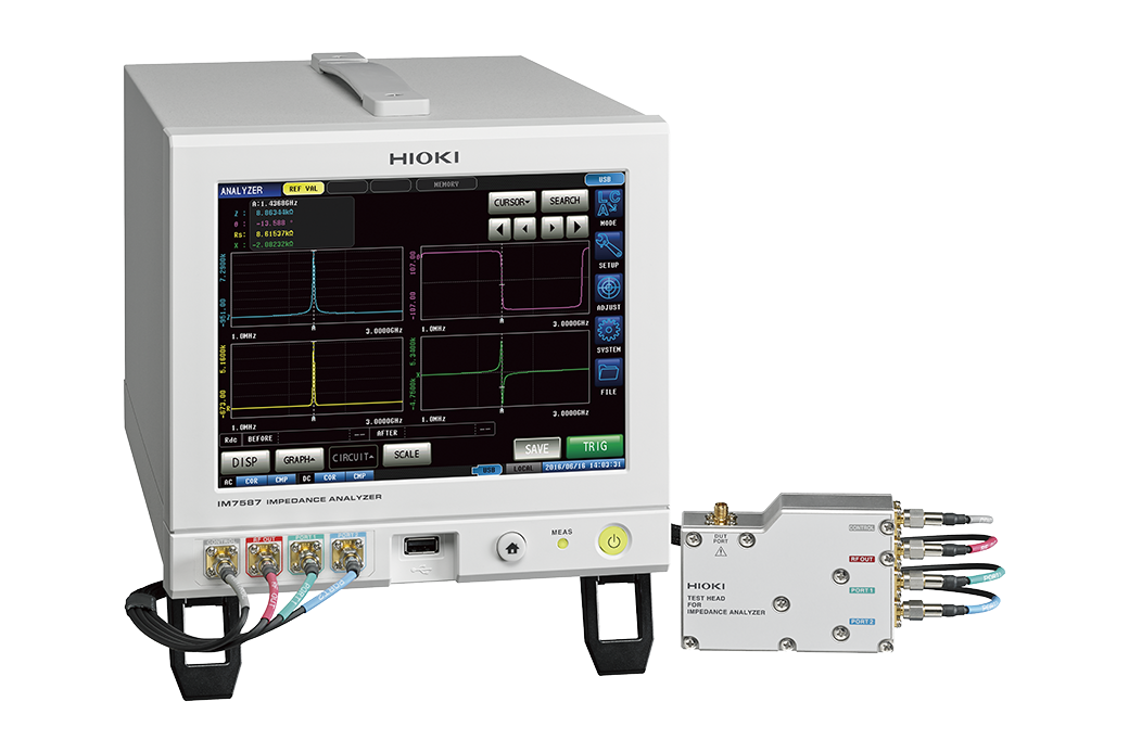
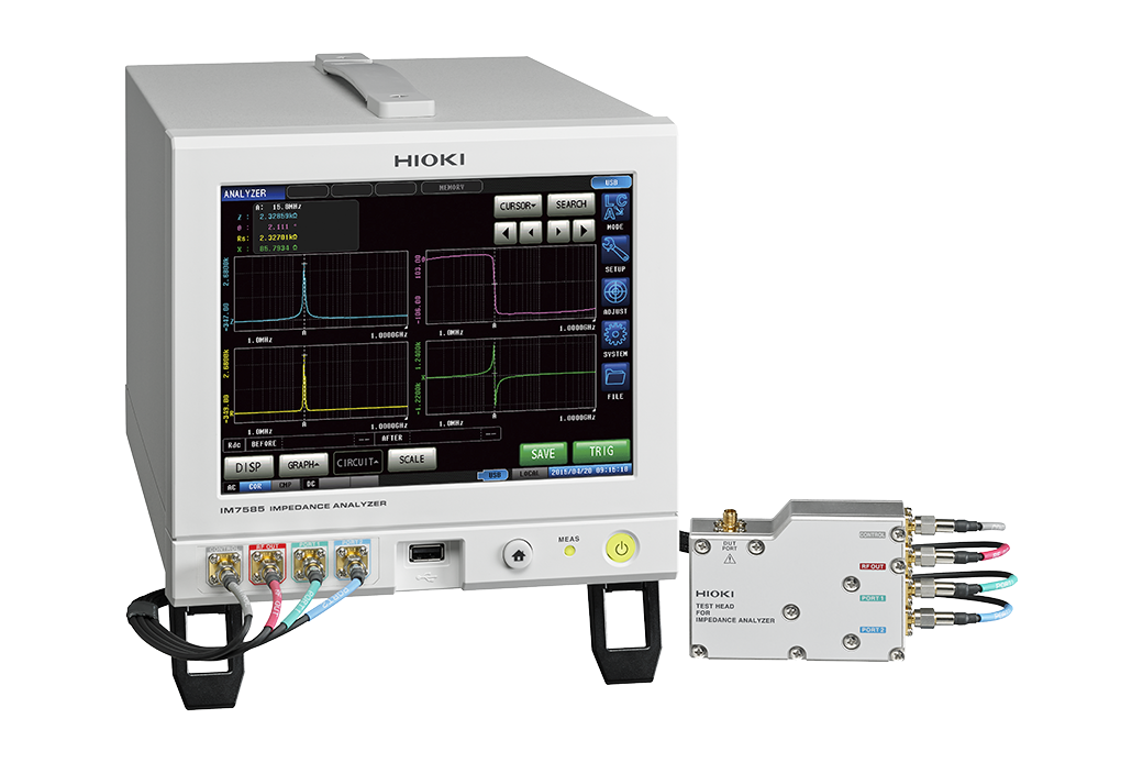
RF I-V method
This method uses the same basic measurement principle as the I-V method. It allows high-frequency impedance measurement by using a circuit that matches the characteristic impedance of a high-frequency coaxial cable and a high-frequency coaxial connector. It’s difficult to use this technique for wideband measurement because the measurement frequency band is limited by the test head’s transformer.
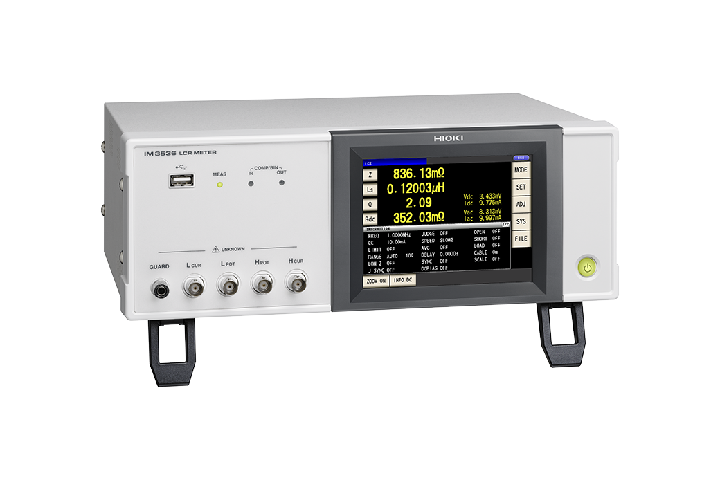
Automatically balanced bridge method
This method uses the same basic measurement principle as the bridge method. It provides coverage for a broad frequency band (1 mHz to 100 MHz). However, that coverage does not extend to high frequencies. Many LCR meters use this technique.
Each method offers its own advantages and disadvantages, so you’ll need to clearly define what kind of impedance you need to measure before choosing the best method to use.
Using an impedance meter
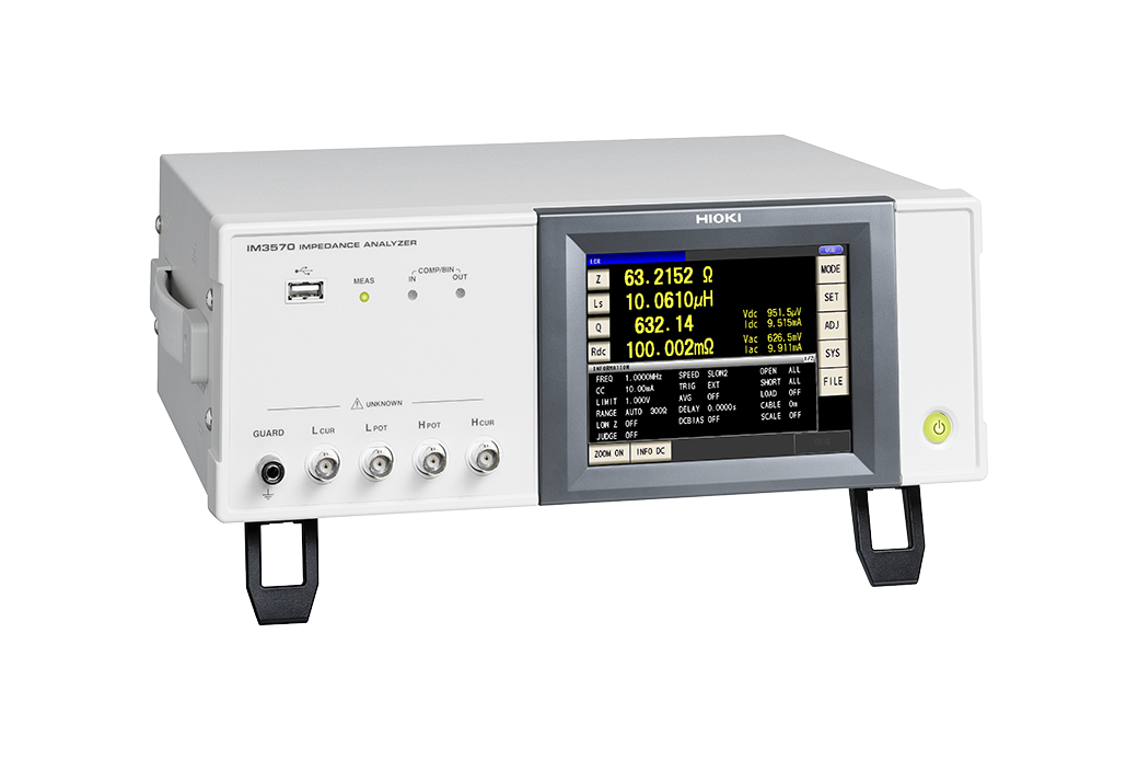
The method used to measure impedance depends on the instrument being used. For example, Hioki’s LCR Meter IM3523A can measure impedance with a high degree of accuracy across a wide range of measurement frequency settings.
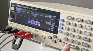 40 Hz measurement
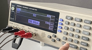 200 Hz measurement
In addition to normal measurement, this instrument can continuously and quickly measure different parameters under different conditions (measurement frequency and signal level).
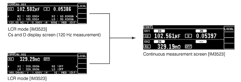 C-D+ESR Measurement of Capacitors
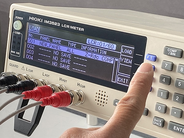
It can also save up to 60 sets of measurement conditions and up to 128 correction values for open/short correction and cable length correction. Groups of settings can be quickly loaded at once to improve work efficiency.
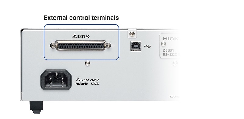
Furthermore, the instrument’s external control terminals let you build automated testing lines more quickly.
Causes of instability in impedance measurement
Depending on the measurement method in use, impedance meters may return a different value each time a measurement is made. If your impedance meter’s measured values fail to stabilize, check the following:
Parasitic components of the components being measured
In addition to the design values for resistance and reactance, components have parasitic components that cause variability in measured values. Even differences in the length of the leads connected to components and the distance between them can cause measured values to vary.
Measurement environment
Impedance measurement results are affected by a variety of conditions, including the temperature of not only resistors, but also capacitors and inductors, as well as probe capacitance and stray capacitance.
This characteristic necessitates steps such as maintaining a consistent measurement environment and averaging multiple measurements instead of using a single measurement to determine the value.
DC bias
DC bias is a minuscule voltage that occurs in measuring instruments and circuits. For example, it occurs when the probe and wire are made from different materials. The resulting thermal electromotive force causes DC bias.
Summary
Impedance quantifies resistance to an AC current, and its measurement requires a dedicated instrument. Since there are a variety of measurement methods, it’s important to choose the best method based on your purpose and each method’s advantages and disadvantages.
Impedance measurement is extremely delicate and prone to variability due to factors including frequency, the measurement environment, and DC bias. This characteristic necessitates steps such as averaging multiple measurements.