Verify Fault Ride-Through (FRT) Capabilities in Equipment and PV Systems
Fault Ride-Through (FRT)
To ensure critical equipment continues to be up and running despite power quality problems such as voltage dips, companies must make sure that adequate ride-through capability is included when the equipment is purchased. Customers then use the fault ride-through or FRT capability curves that manufacturers provide so that they can properly and regularly evaluate the equipment minimize future issues.
FRT in PV Systems
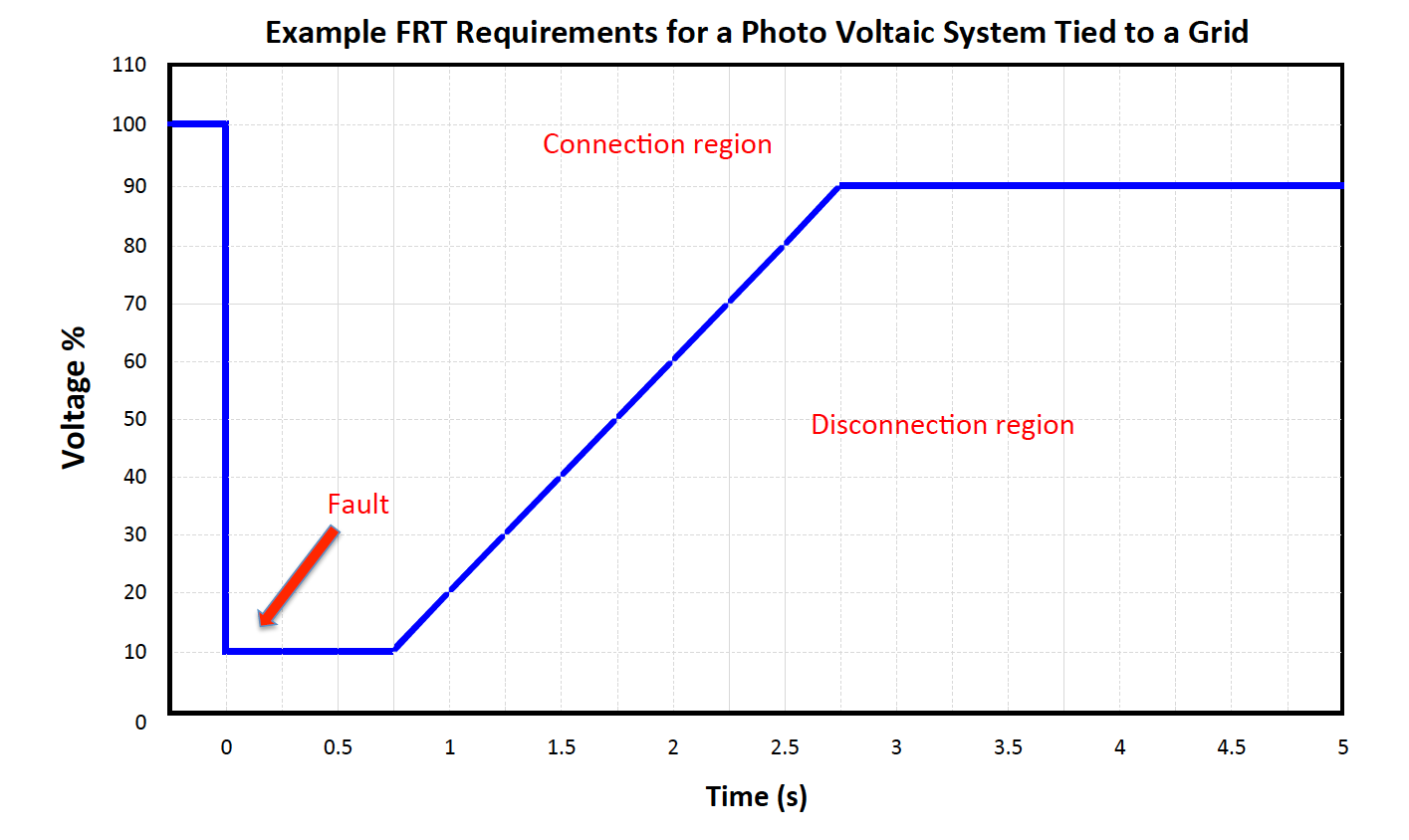
Similarly, abruptly taking a high-capacity, grid-tied photovoltaic (PV)
system offline introduces disturbances into the power grid that have a
significant and adverse impact on power quality. To prevent this issue,
the regulations governing such grid-tied systems have been updated to
require PV equipment to incorporate fault ride-through (FRT)
functionality. Also note that FRT grid codes vary from country to country.

How Should FRT Work?
FRT capabilities vary from equipment to equipment, and sometimes it takes a few seconds before the voltage returns to the nominal level. In a PV system, FRT functionality allows it to continue operating even if the grid experiences a period of reduced voltage lasting 1 second or less. Specifically, when the FRT function operates, it becomes necessary to observe the voltage waveform for about 5 seconds after the drop in order to verify the stability of the grid. A power quality analyzer capable of capturing the power situation both before and after such an event is useful in order to meet this requirement.
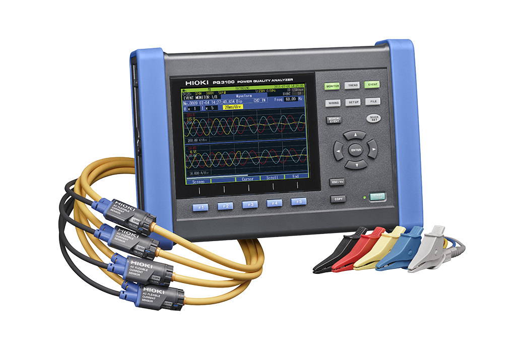
A Solution in the PQ3100 Power Quality Analyzer
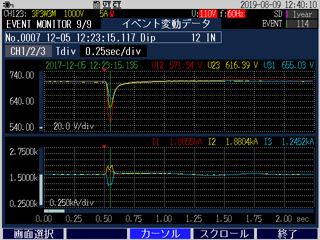
The PQ3100 Power Quality Analyzer detects power quality events such as voltage sags and provides a 11.2 second waveform surrounding the event (1.2 seconds before and 10 seconds after), letting you confirm proper restoration of the voltage level within the necessary timeframe using a single instrument. This more than covers the 5 second requirement for confirming stability of the grid.
Equipment with FRT capabilities will show voltage recovering quickly, while equipment with no FRT capabilities will show voltage rising back slowly and oftentimes not according to standards.
Measurement Setup
1 Select the AC or AC/DC clamp and flexible sensors appropriate for the equipment or PV system under test. Hioki sensors can be directly powered by the PQA without the need for batteries or separate AC adapters to streamline the work environment
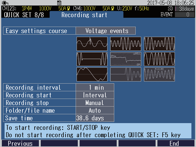
2. Use the PQ3100’s QuickSet wizard to easily and correctly wire, configure, and measureWide range sensors that measure accurately even at 1/100 of the rated current, letting you use a single clamp to cover from very low to very high currents
3. Use the free GENNECT Cross for Windows software application to report the voltage recovery and verify proper operation of equipment