High-Voltage, Large-Current, and High-Power Measuring to Determine Solar Inverter Performance
Solar inverters with high voltage, large current, and high power are becoming increasingly common. This is done to increase power generation efficiency and reduce installation costs. This article introduces measurement of high voltages, large currents, and high power values when evaluating solar inverter efficiency.
Index
- What's the efficiency of a Solar inverter
- What tools are appropriate for evaluating solar inverter efficiency?
- Measurement of large currents
- Measurement of high voltages
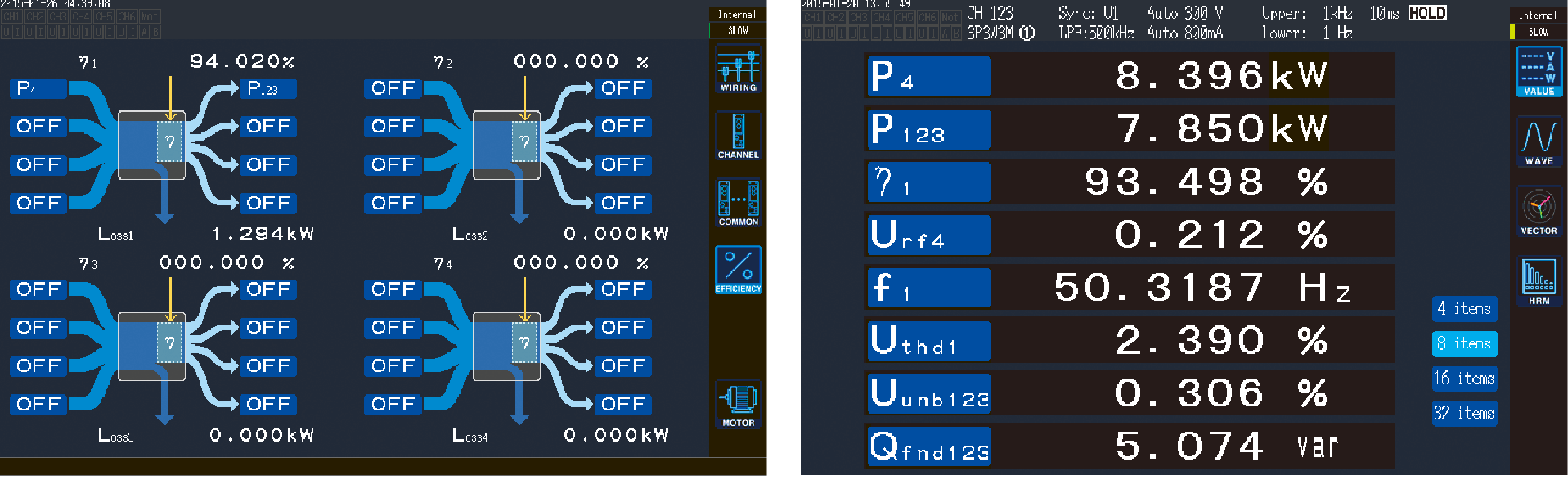
- Ascertaining power loss at various locations in solar inverters
- Instrument frequency characteristics
- Measurement tools provided by HIOKI
What's the efficiency of a Solar inverter
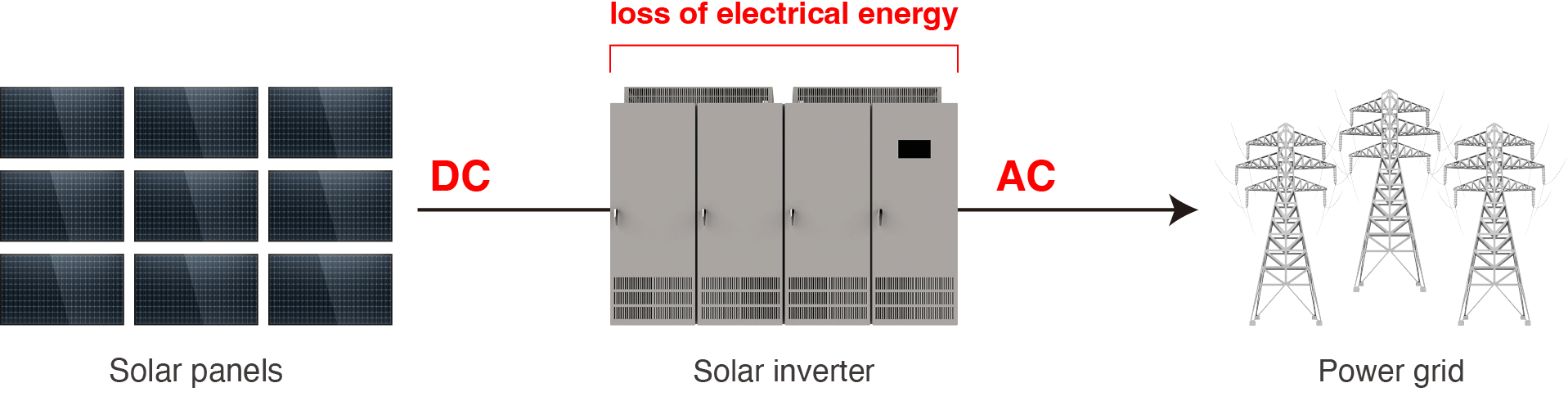
Solar inverters convert electrical energy into an appropriate state depending on the intended application. For example, they may convert DC power generated by solar panels into AC power for transmission to the electrical power grid. Such conversion is accompanied by the loss of electrical energy. Efficiency serves as an important indicator of solar inverter performance. Efficient solar inverters are able to make effective use of generated electrical energy with only small losses.
What tools are appropriate for evaluating solar inverter efficiency?
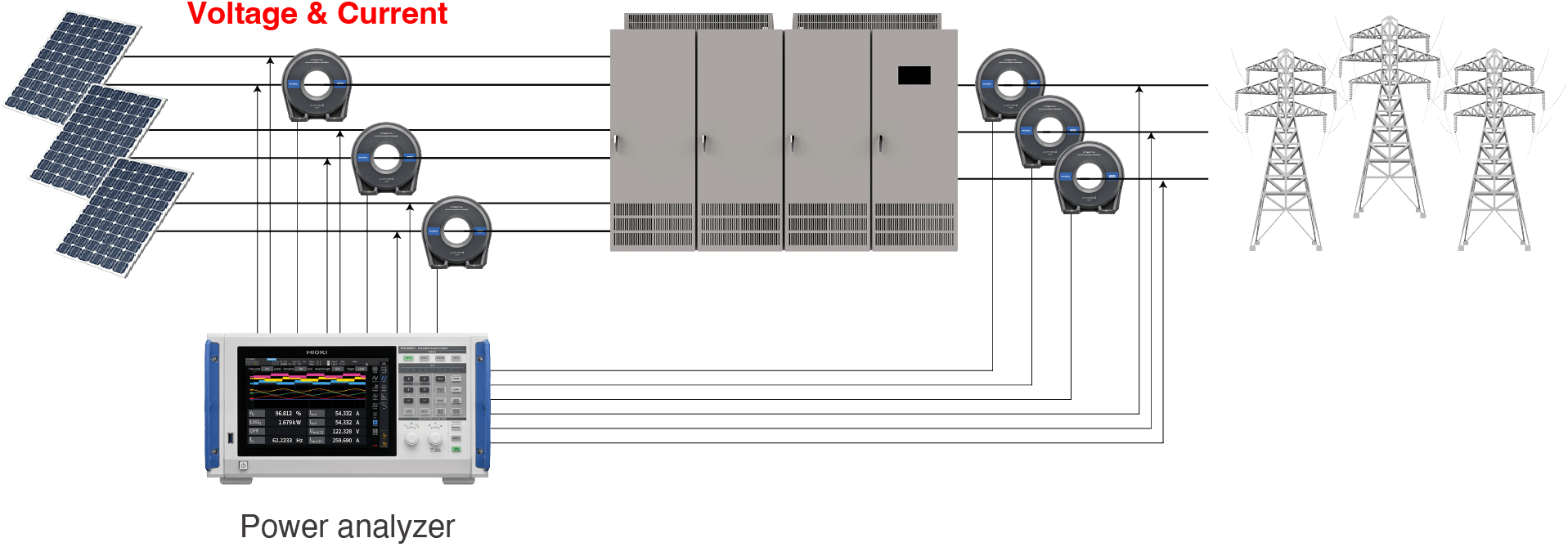
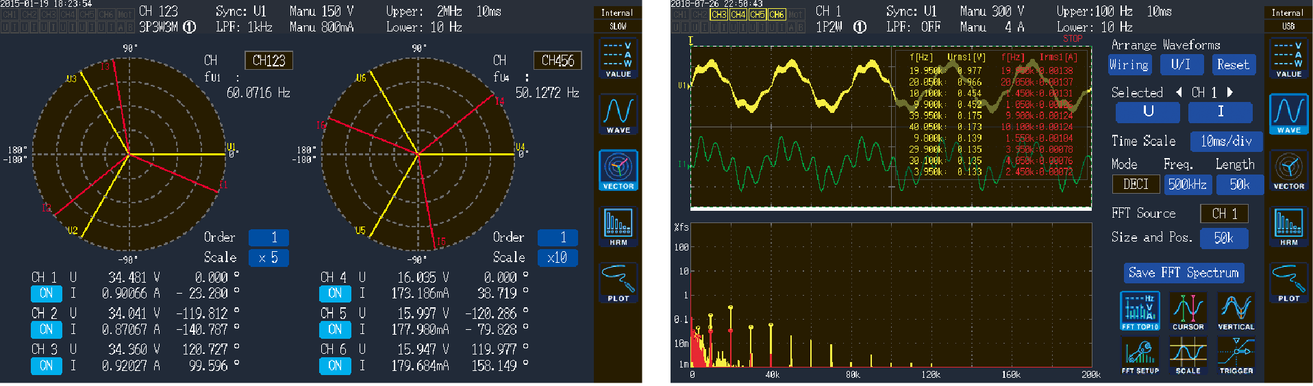
Power analyzers are ideal for evaluating efficiency. These instruments provide calculation functionality for analyzing power. By simultaneously acquiring voltage and current values from multiple locations in a target circuit and using the resulting data to perform calculations, they can analyze various power components.
Example of power analysis with a power analyzer
Measurement of large currents
There are two methods for measuring current: current sensors and direct wiring. However, it’s difficult to measure large currents using the direct wiring method. The current sensor method is suited to measuring large currents. This method has advantages in terms of not only current magnitude, but also measurement accuracy.
Measurement example
using the current sensor method
A current sensor is connected to the wiring on the measurement target. This reduces the effects of wiring and loss on the side of the measurement instrument. This allows measurements with wiring conditions that are close to the actual operating environment of a highly efficient system.
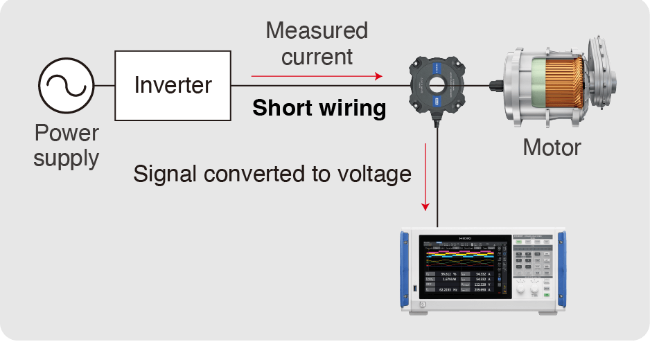
Small insertion loss
Little effect from routing
Measurement example
using the direct wiring method
The wiring of the measurement target is routed for connecting to the current input terminal. However, this results in an increase in the influence of power loss from wiring resistance and capacitive coupling, and meter loss ing due to shunt resistance. All of this loss leads to larger degradation in accuracy.
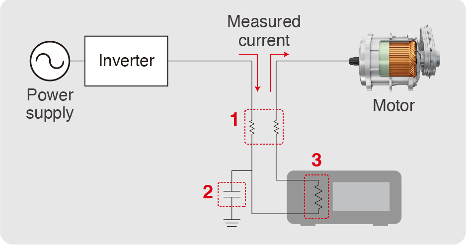
1: Wiring resistance loss due to long routing
2: Leakage current loss due to capacitive coupling
3: Instrument loss due to shunt resistance
fundamental wave reactive power Qfnd, DC ripple rate, and 3-phase unbalance rate.
Temperature after detecting current continuously for 10 minutes using each method
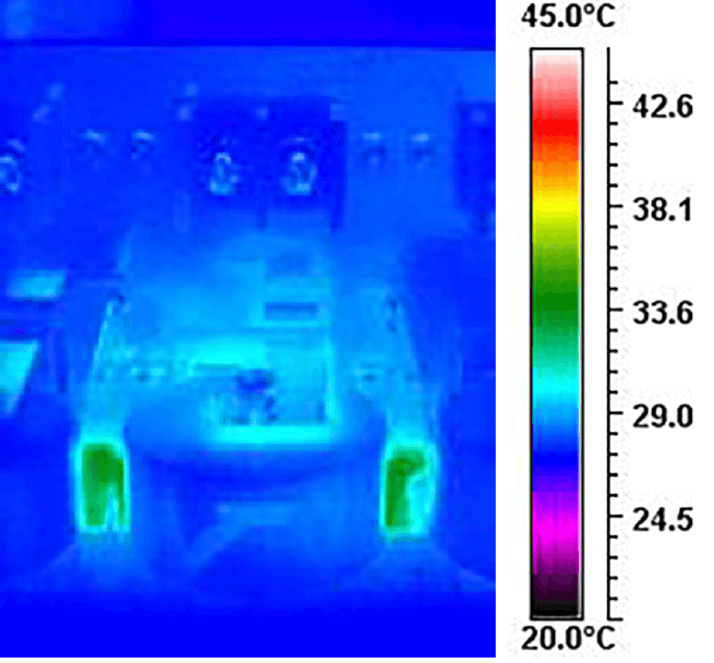
Current sensor method
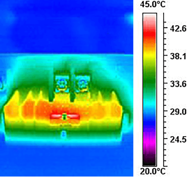
Direct wiring method
Current is detected using a shunt resistor.
The heating of the shunt resistor affects measured values.
Measurement of high voltages
Right: FFT analysis of conductive noise from 2 kHz to 150 kHz as generated by a device such as a switching power supply
When measuring high voltages of 1000 V or greater using a power analyzer, the voltage is divided using a high-voltage differential probe, voltage transformer (VT, PT), or high-voltage divider. Voltage transformers are poorly suited to the measurement of DC as well as square waves and distorted waves like PWM, while high-voltage differential probes suffer from measurement error on the order of several percentage points. High-voltage dividers, which can precisely detect both DC and rectangular and distorted waves like PWM, are perfect for determining improvements in efficiency on the scale of 0.1%.
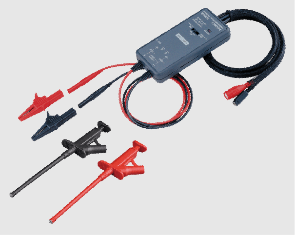
High-voltage differential probe 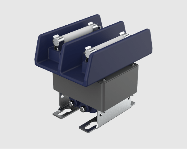
Voltage transformer (VT, PT) 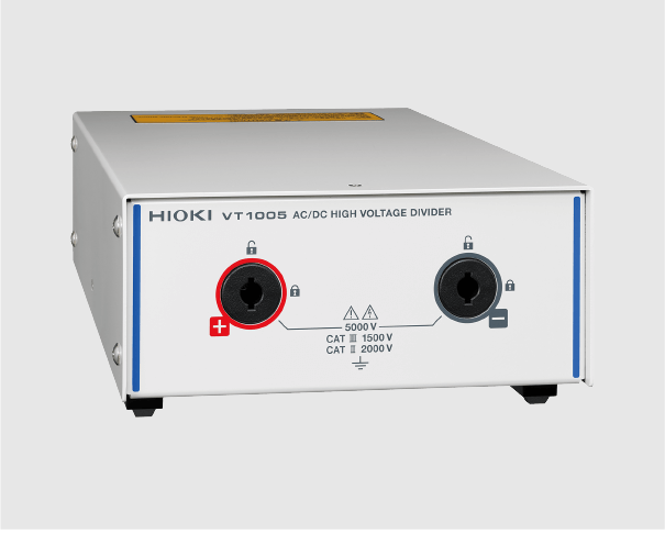
High-voltage divider
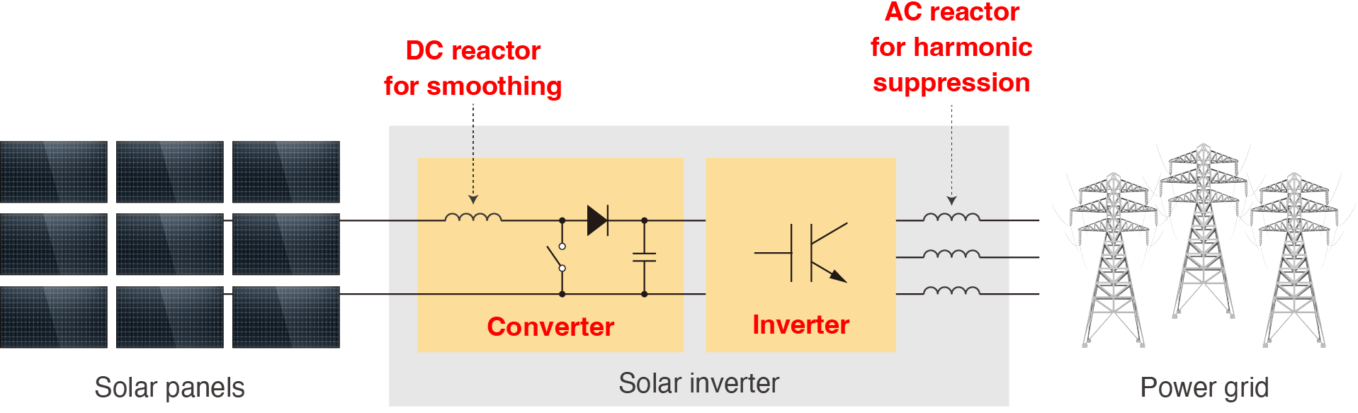
Ascertaining power loss at various locations in solar inverters
For example, input power and output power on both sides of a smoothing DC reactor are affected by switching frequencies and harmonics resulting from switching control. To accurately measure power loss at a reactor, you’ll need to measure not only DC and 50 Hz/60 Hz, but also harmonic components.
Instrument frequency characteristics
Instruments have frequency characteristics, for example fluctuations in amplitude error and phase error in the harmonic band. In order to accurately measure power that contains a variety of frequency components, it’s necessary to ascertain error not only at representative points like DC and the frequency in the commercial line (50 Hz/60 Hz), but also in the harmonic band.
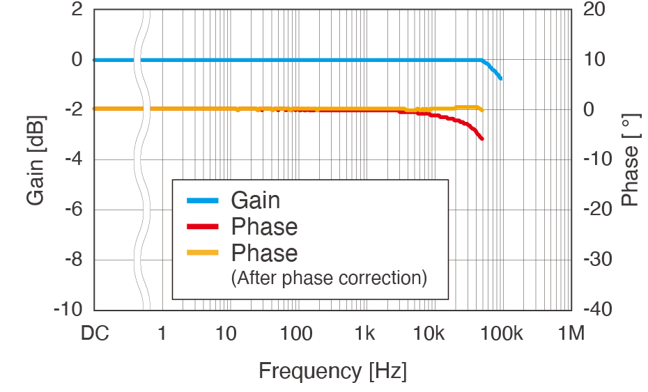
Frequency characteristics
AC/DC CURRENT SENSOR CT6877A(HIOKI)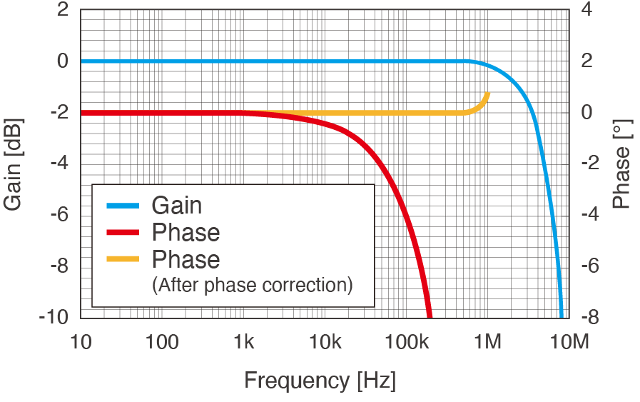
Frequency characteristics
AC/DC HIGH VOLTAGE DIVIDER VT1005(HIOKI)
What is phase correction?
Harmonic power can be accurately measured by correcting current sensor and divider phase error with a power analyzer.
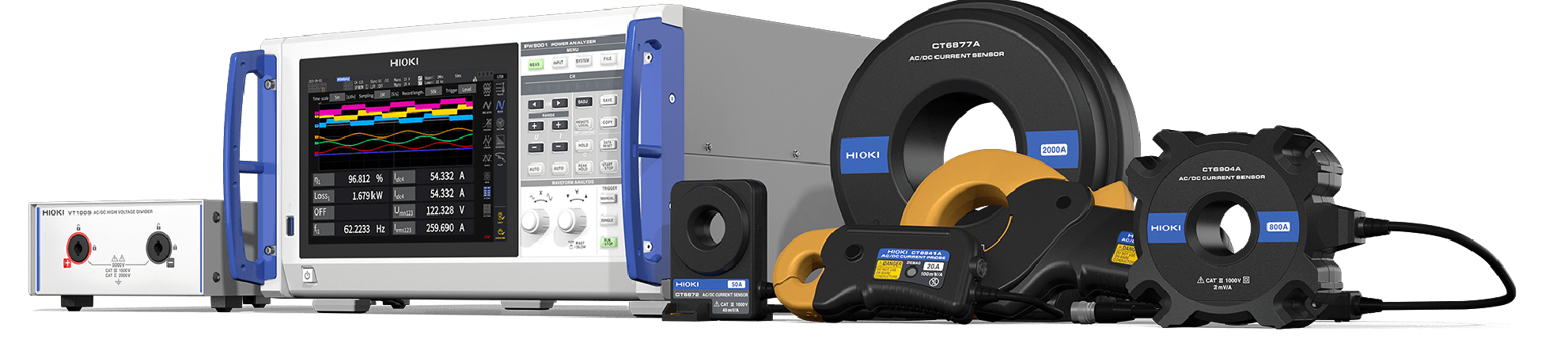
Measurement tools provided by HIOKI
In order to accurately measure power, performance is critical—not only of the power analyzer, but also of current sensors and dividers. Hioki develops and manufactures products ranging from sensors to power analyzers in-house. We realize accurate power measurement by improving product performance and compatibility.
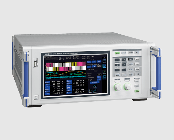
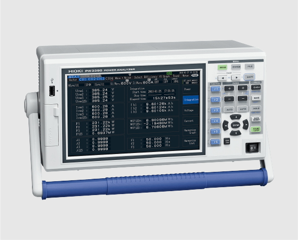
We offer a line of three power analyzers, from the flagship PW8001 to the portable PW3390. The PW8001 supports direct input of 1500 V DC or 1000 V AC.
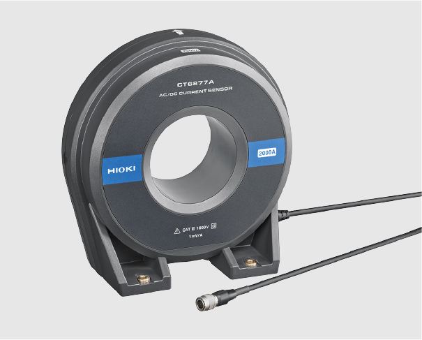
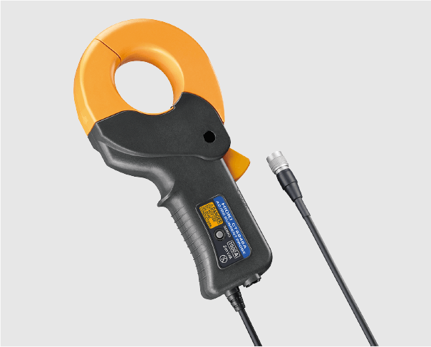
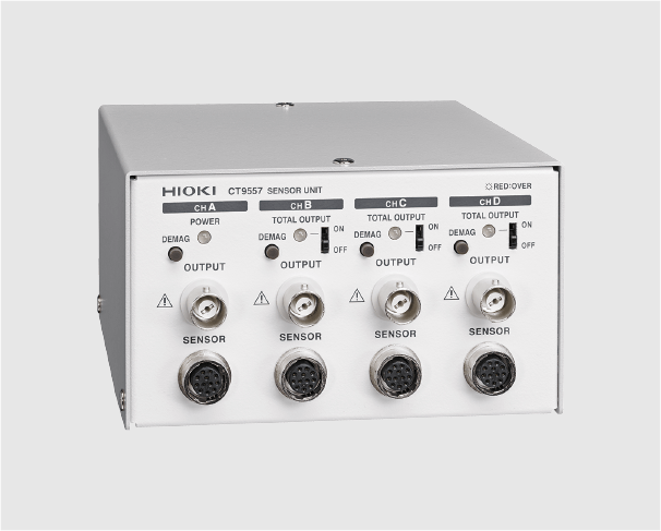
Current Sensors
We also offer a line of clamp and pass-through current sensors. Clamp models can measure up to 1000 A, while pass-through models can measure up to 2000 A. The CT9557 can add together output from multiple current sensors, allowing measurement of up to 8000 A in multi-wire line circuits.
High-voltage dividers
The VT1005 divides and outputs voltages of up to 5000 V. Thanks to measurement accuracy that’s superior to that of high-voltage differential probes, the device is able to measure high voltages accurately.