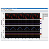
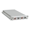
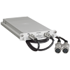
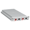
MEMORY HiCORDER MR8740T
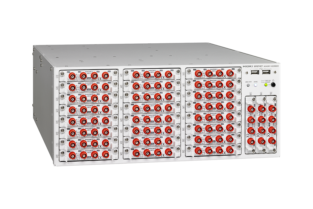
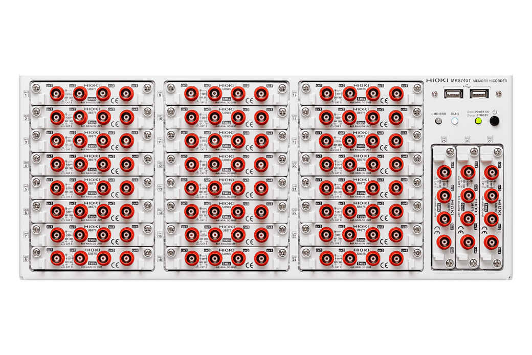
Max. 108 Analog Channels, Reduce Inspection Data Transfer Time to Zero
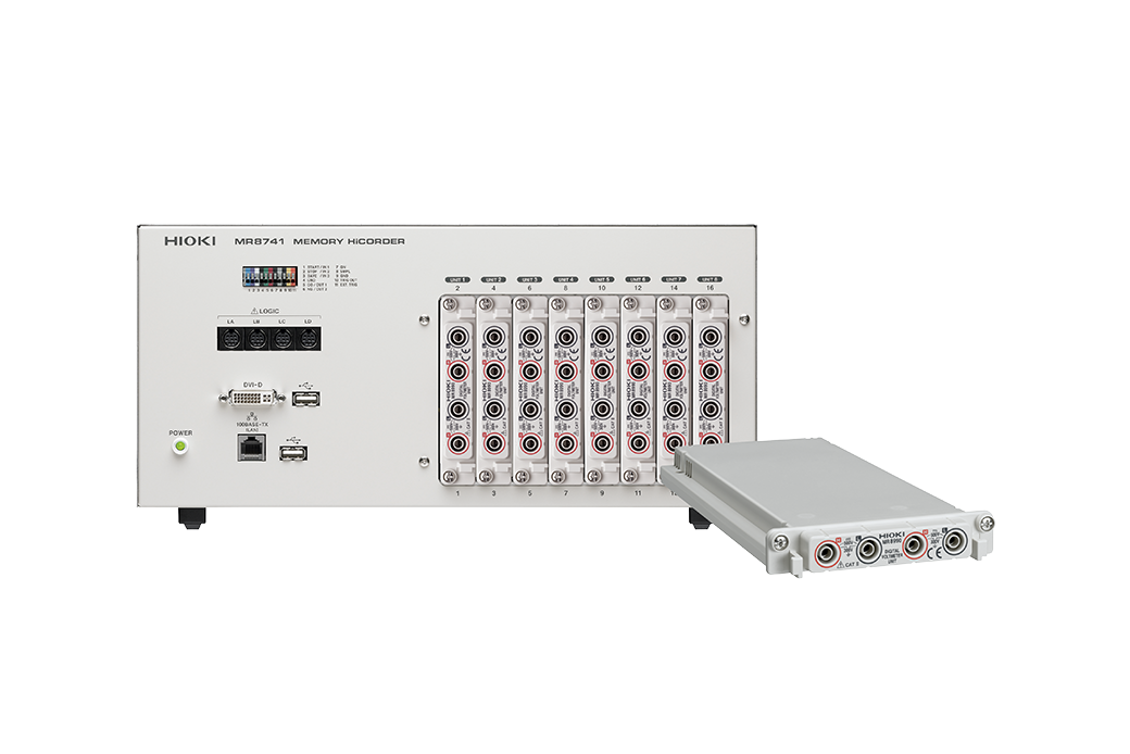
The MR8740T (MR8740-50) is rack-mountable data acquisition system that delivers high-speed, multi-channel measurements over maximum of 108 channels. Generate simulated signals and record at the same time using plug-and-play input units, making the waveform recorder ideal for evaluating multi-signal devices such as vehicle electronic control units (ECU).
Key Features
- Ideal for multipoint inspection of high performance boards such as ECU
- 108ch analog to 96ch analog + 48ch logic input
- Reduce time required to save to external media to max.1/100 compared with conventional method
- 20 MS/s simultaneous sampling on all channels
- Safe measurement with all analog inputs isolated
- Supports 4K monitor to display multi-channel waveforms without overlapping
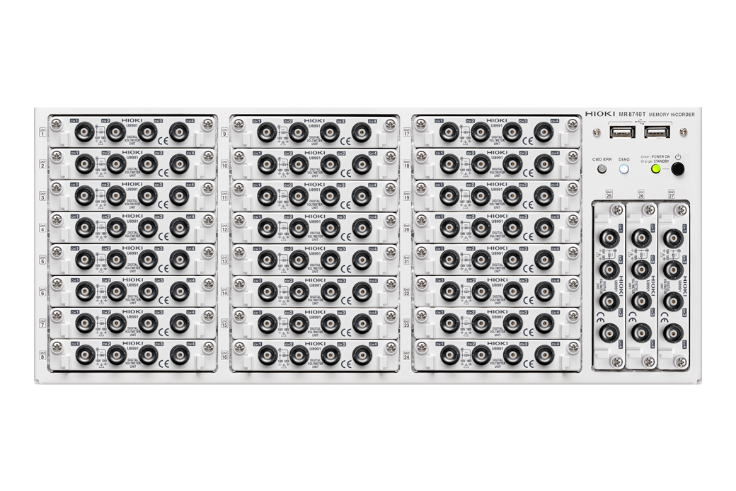
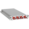
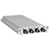
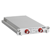
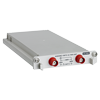
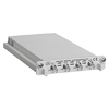
- Measure 4 channels with 1 unit (4 ch analog Unit U8975, 4 ch DVM Unit U8991)
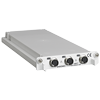
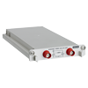
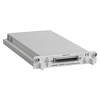
- Generate constant voltage, constant current, and simulated resistance (VIR Generator Unit U8794)
Model No. (Order Code)
| MR8740-50 | Max. 108ch, 1GW memory, main unit only |
|---|
ECU Testing
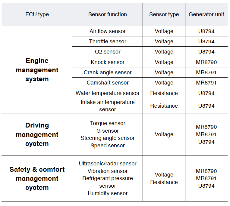
ECUs are connected to a large number and wide variety of sensors. The MR8740T can be installed with signal generation unit to simulate these sensors. By measuring the simulation results with a measurement unit at the same time, you can perform all steps from signal generation to measurement with a single device. The U8794 VIR GENERATOR UNIT also offers resistance output to enable thermistor circuit testing.

Ideal for testing that requires simulated signals
When used as an ECU testing device, generate simulated signals from various sensors, which is indispensable for testing electronic parts and maintaining equipment. Record signals captured by various sensors to identify air flow, throttle, torque, speed, vibration, humidity, etc.
Basic specifications
| Number of input units | Max. 27 slots | |||||
|---|---|---|---|---|---|---|
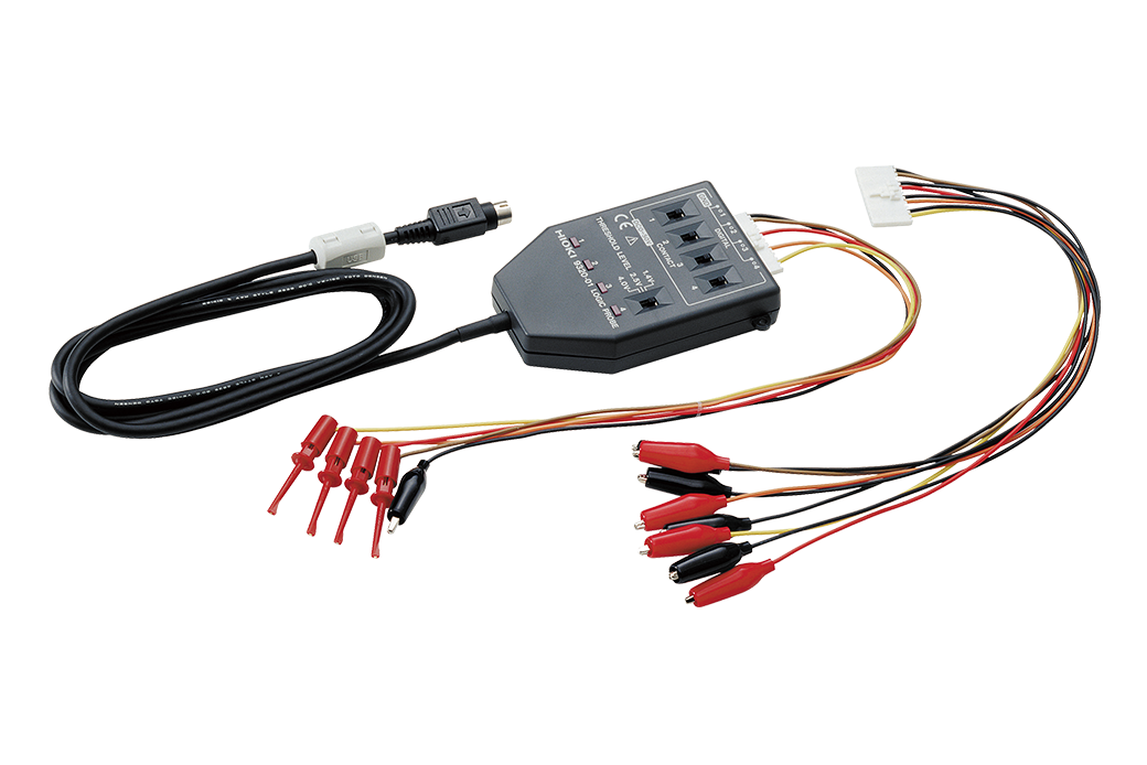
| Number of channels | [Using the U8975] Max. 108 ch analog, or 96 ch analog + 48 ch logic (when used in combination with U8975 + 8973) [Using the 8966] Max. 54 ch analog, or 48 ch analog + 48 ch logic (when used in combination with 8966 + 8973) *Logic unit 8973 is limited to slots 25 to 27, up to 3 units. *Analog unit channels are isolated from each other and from chassis. Logic unit channels share a common GND with chassis. |
|||||
| Measurement ranges | 100 mV to 400 V f.s., 12 ranges, resolution : 1/2000 of range (when using 8966) 4 V to 200 V f.s., 6 ranges, resolution : 1/32000 of range (when using U8975) 100 mV to 1000 V f.s., 5 ranges, resolution : 1/1000 000 of range (when using MR8990) 1 V, 10 V, 100 V f.s., 3 ranges, resolution : 1/1000 000 of range (when using U8991) |
|||||
| Max. allowable input | 1000 V DC/700 V AC (when using the U8974), 400 V DC (when using the 8966), 200 V DC (when using the U8975), 40 V DC (when using the U8978) | |||||
| Frequency characteristics | DC to 5 MHz (-3 dB, when using 8966) | |||||
| Max. sampling speed | 20 MS/s, all ch simultaneous, external sampling: 10 MS/s | |||||
| Measurement functions | Memory (high-speed recording) | |||||
| Memory capacity | Total of 1 G Word installed, 16 MW/ch (when using 8966), 8 MW/ch (when using U8975 or MR8990), 4 MW/ch (when using U8991) | |||||
| Internal storage | SSD 480 GB | |||||
| Removable storage | USB memory stick ×8 | |||||
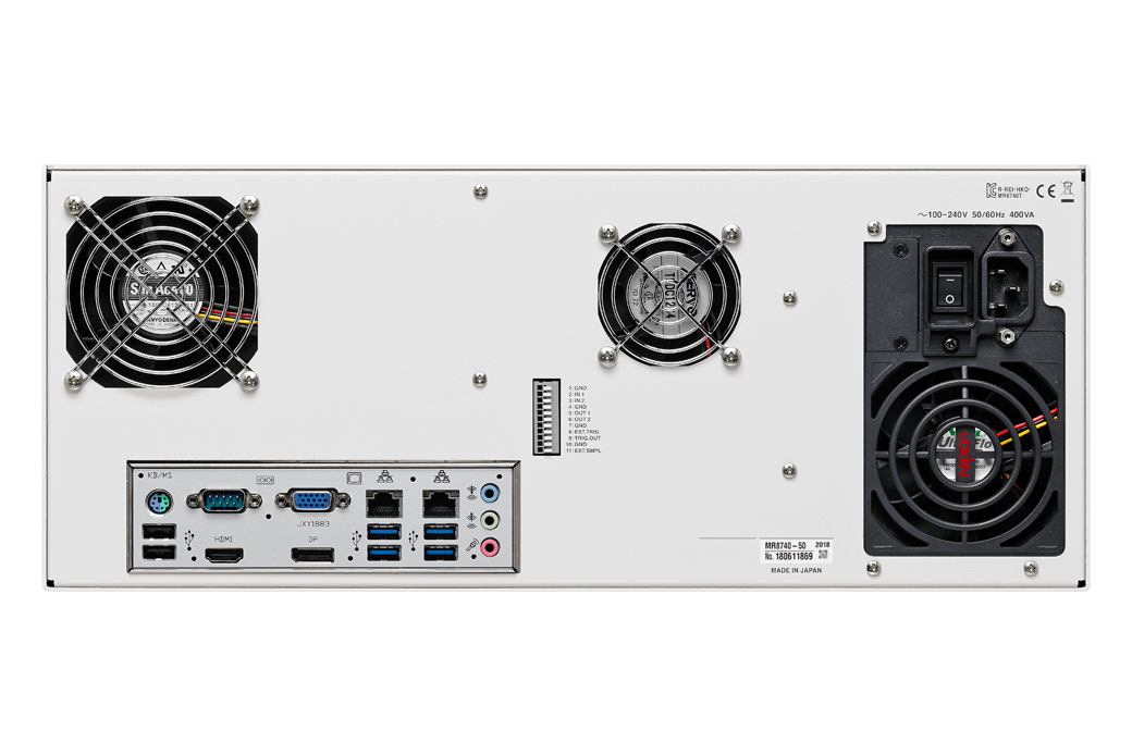
| Monitor output | VGA, HDMI, Display Port, Recommended resolution 1920 × 1080 dot or more | |||||
| External interfaces | [LAN] 1000 BASE-T, 100 BASE-TX, 10 BASE-TX (2 port) (DHCP and DNS support, FTP server/cliant, HTTP server) [USB] USB 3.0 Series A receptacle × 4, USB 2.0 ×4 |
|||||
| Power supply | 100 to 240 V AC, 50/60 Hz (400 VA max.) | |||||
| Dimensions and mass | 426 mm (16.77 in)W × 177 mm (6.97 in)H × 505 mm (19.88 in)D, 14.0 kg (493.8 oz) (main unit only) | |||||
| Included accessories | Power cord ×1,Quick Start Manual (booklet) ×1, blank panel (blank slot only), rack installation hardware | |||||
Storage media (1)
* The CF card includes a PC card adapter.
*Use only the storage media sold by HIOKI. Compatibility and performance are not guaranteed for storage media made by other manufacturers. You may be unable to read from or save data to such media.
16 GB, long-life, high-reliability SLC flash memory
PC Software (1)
Output cable (2)
* Please contact your local HIOKI distributor for connectors that support Model MR8791.
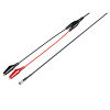
Max. rated voltage to earth: 33 Vrms AC or 70 V DC, SMB to alligator clip, 1.5 m (4.92 ft) length
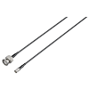
Max. rated voltage to earth: 33 Vrms AC or 70 V DC, SMB to BNC terminal, 1.5 m (4.92 ft) length
Input modules (15)
* Input cords not included. Please purchase them separately.
* Note: Current Unit 8971 Max. 4 modules can be installed in the MR8740-50
Note: Logic Unit 8973 Max. up to 3 units (slots 25 to 27 only)
Output modules (4)
* Input cords not included. Please purchase separately.
* Configure settings with communication commands.
SCI Monitor 4.0 (0)
HSCI-4.0-CAN FD
HSCI-4.0-SENT
HSCI-4.0-LIN
CAN monitors, LIN monitors, and SENT monitors that are the same size as the MR8740T unit can be purchased from Nihon System Eight Co., Ltd. Power is supplied to a monitor when it is installed on the MR8740T. Note that it will not be possible to record or analyze the data with the MR8740T or HIOKI software. Please contact Nihon System Eight for additional information.
http://nse-inc.co.jp/
INPUT CORD (A) (4)
* Voltage is limited to the specifications of the input modules in use
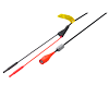
• Flexible φ 4.1 mm (0.16 in) thin dia.
• Cable allowing for up to 600 V input
• 1.8 m (5.91 ft) length
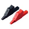
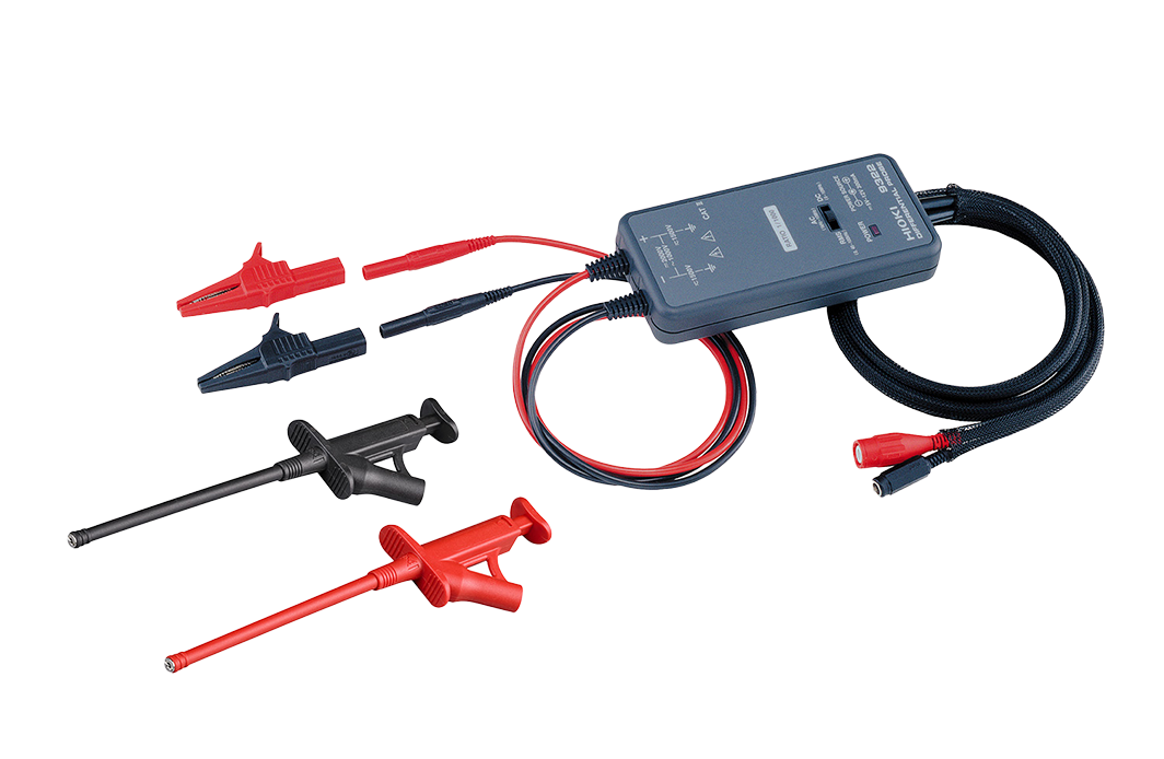
Red/black set attaches to the ends of the Connection Cord L9790
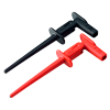
Red/black set attaches to the ends of the Connection Cord L9790
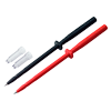
Red/black set attaches to the ends of the Connection Cord L9790
INPUT CORD (B) (3)
* Voltage is limited to the specifications of the input modules in use
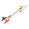
•φ 5.0 mm (0.20 in) dia
•Cable allows for up to 600 V input
•1.8 m (5.91 ft) length
•Includes detachable large alligator clips
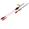
•φ 5.0 mm (0.20 in) dia.
•Cable allows for up to 300 V input
•1.7 m (5.58 ft) length
•Small alligator clip
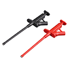
Attaches to the tip of the banana plug cable, Red/Black: 1 each, 185 mm (7.28 in.) length, CAT II 1000 V
INPUT CORD (C) (2)
* This probe does not expand the maximum rated voltage above ground of an isolated input.
INPUT CORD (D) (2)
* Voltage to ground is within this product’s specifications, separate power source is also required.
Custom cable (0)
*For P9000. Inquire with your local Hioki distributor.
(1) Bus powered USB cable
(2) USB(A)- Micro B cable
(3) 3-prong cable
INPUT CORD (E) (2)
* Voltage to ground is within this product’s specifications, separate power source is also required.
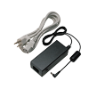
100 to 240V AC
INPUT CORD (F) (6)
* Voltage input via banana terminals limited by the voltage specifications of the respective input unit.
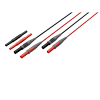
Expands the length of L4930/4940, 1.5 m (4.92 ft) length
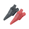
Attaches to the tip of the L4930/4940, CAT IV 600 V, CAT III 1000 V
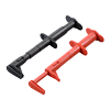
Attaches to the tip of the L4930/4940, CAT III 600 V
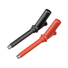
Attaches to the tip of the L4930/4940, CAT III 1000 V
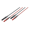
Banana plug - banana plug, 1.5 m (4.92 ft) length, red/black each 1

Attaches to the tip of the banana plug cable, Red/Black: 1 each, 185 mm (7.28 in.) length, CAT II 1000 V
INPUT CORD (G) (1)
*For the MR8990 *Voltage is limited to the specifications of the input modules in use
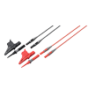
70 cm (2.30ft) length, detachable large alligator clips or needle tips are bundled, CAT IV 600V, CAT III 1000V
Non-contact voltage measurement (0)
Other options for input (2)
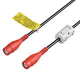
Cord has insulated BNC connectors at both ends, 1.6 m (5.25 ft) length
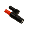
Receiving side banana (female), output BNC (male)
Temperature sensor (0)
THERMOCOUPLE
*For reference only. Please purchase locally.
Logic signal measurement (3)
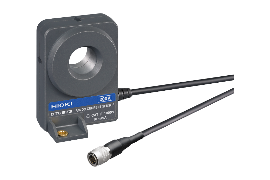
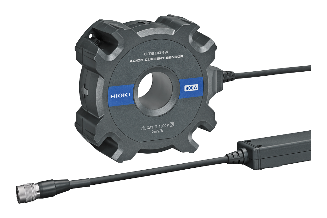
Up to 200 A (High precision) (6)
Separate power supply (CT955x) is required in order to use a high-precision current sensor.
Only sensors with ME15W (12-pin) terminals can be connected to the CT955x.
The separately available CONVERSION CABLE CT9900 is required in order to use a sensor with PL23 (10-pin) terminal.
Up to 1000 A (High precision) (7)
Separate power supply (CT955x) is required in order to use a high-precision current sensor.
Only sensors with ME15W (12-pin) terminals can be connected to the CT955x.
The separately available CONVERSION CABLE CT9900 is required in order to use a sensor with PL23 (10-pin) terminal.
PL23 (10-pin) - ME15W (12-pin) conversion (1)
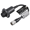
Convert PL23 (10-pin) terminal to ME15W (12-pin) terminal
POWER SUPPLY for Current Sensors (4)
*A separate power supply (CT955x) is required in order to use a high-precision current sensor.
*Only sensors with ME15W (12-pin) terminals (-05 type) can be connected to the CT955x. *The separately available Conversion Cable CT9900 is required in order to use a sensor with PL23 (10-pin) terminal.

Cord has insulated BNC connectors at both ends, 1.6 m (5.25 ft) length
Directly connect currents sensors (2)
ME15W (12-pin) - PL23 (10-pin) conversion
*The separately available Conversion Cable CT9901 is required in order to use a high-precision current sensor equipped with a ME15W (12-pin) terminal (-05 type) with the Current Unit 8971 (which is designed for use with the MR8847, MR8827, and MR8740).
*While the CT955x is not required in order to use a sensor equipped with a PL23 (10-pin) terminal with the 8971 or 8940, the Conversion Cable 9318 (which comes with the 8971) is required for that setup.
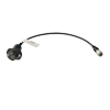
To connect the CT6841-6846, CT6865/63/62, 9709, 9272-10 to the 8971/40/51, 38 cm (14.96 in) length
Precautions when connecting a high-precision current sensor to a Memory HiCorder (0)
Connecting to the MR8847A / MR8827 / MR8740
• High-precision current sensor (ME15W) + CT9901 + 9318 → CURRENT UNIT 8971
• High-precision current sensor (ME15W) + CT955x + BNC cable → except CURRENT UNIT 8971
• High-precision current sensor (PL23) + 9318 → CURRENT UNIT 8971
• High-precision current sensor (PL23) + CT9900 + CT955x + BNC cable → except CURRENT UNIT 8971
10 mA class to 500 A (High speed) (4)
Precautions for connecting current sensors and current probes (0)
* Some combinations may not allow the devices to be connected simultaneously.
* Up to 4 CURRENT UNITS 8971 can be connected to the MEMORY HiCORDER main unit, and up to 8 current sensors can be used, including those connected to the PROBE POWER UNIT Z5021.
* There is no limit if you connect a current sensor to the voltage input analog unit.
Leak Current (2)
*For commercial power lines, 50/60 Hz
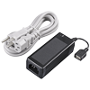
100 V to 240 V AC

