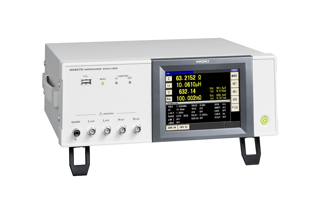
IMPEDANCE ANALYZER IM3570
Single Device Solution for High Speed Testing and Frequency Sweeping
Hioki LCR Meters and Impedance Analyzers range from 1mHz to 3GHz devices to suit a wide range of applications in the testing of electronic components. The IM3570 is ideal for use in applications requiring low-ESR measurement on the order of several milliohms, for example testing of functional polymer capacitors, due to its superior low-impedance repeatability.
Product Video
Key Features
- Continuous LCR/DCR/sweep measurements and high-speed testing achieved with one instrument
- High-speed testing, achieving maximum speeds of 1.5ms (1 kHz) and 0.5ms (100kHz) in LCR mode
- High-accuracy measurements, basic accuracy of Z parameter: ±0.08%
- Perfect impedance analyzer for testing the resonance characteristics of piezoelectric elements, C-D and low ESR measurement of functional polymer capacitors, DCR and L-Q measurement of inductors (coils and transformers)
- Perform frequency sweeps, level sweeps, and time interval measurements in analyzer mode
Model No. (Order Code)
| IM3570 |
|---|
Impedance Analyzer IM3570: Measuring the resonance characteristics of a piezoelectric element
The IM3570, which serves as both an LCR meter and an impedance analyzer, can generate pass/fail judgments on the resonance condition using its frequency sweep measurement and peak comparator functions, and also conduct continuous inspections under different conditions including pass/fail decisions via 1 kHz and 120 Hz LCR testing. In this way, it is possible to make both frequency sweep measurement and LCR measurement with a single instrument.
Application information
Download the sample application and view the Communications Command User Manual.

Accuracy calculation information
Calculate accuracy by simply entering a numerical value.

Basic specifications
| Measurement modes | LCR mode, Analyzer mode (Sweeps with measurement frequency and measurement level), Continuous measurement mode | |||||
|---|---|---|---|---|---|---|
| Measurement parameters | Z, Y, θ, Rs (ESR), Rp, Rdc (DC resistance), X, G, B, Cs, Cp, Ls, Lp, D (tanδ), Q |
|||||
| Measurement range | 100 mΩ to 100 MΩ, 12 ranges (All parameters are determined according to Z) | |||||
| Display range | Z, Y, Rs, Rp, Rdc, X, G, B, Ls, Lp, Cs, Cp : ±(0.000000 [unit] to 9.999999G [unit], Absolute value display for Z and Y only θ : ±(0.000° to 180.000°), D : ±(0.000000 to 9.999999) Q : ±(0.00 to 99999.99), Δ % : ±(0.0000% to 999.9999%) |
|||||
| Basic accuracy | Z ±0.08% rdg. θ: ±0.05° | |||||
| Measurement frequency | 4 Hz to 5 MHz (5 digits setting resolution, minimum resolution 10 mHz) | |||||
| Measurement signal level | Normal mode: V mode/CV mode: 5 mV to 5 Vrms (up to 1 MHz) 10 mV to 1 Vrms (1.0001 MHz to 5 MHz), 1 mVrms steps CC mode: 10 μA to 50 mArms (up to 1 MHz) 10 μA to 10 mArms (1.0001 MHz to 5 MHz), 10 μArms steps Low impedance high repeatability mode: V mode/CV mode: 5 mV to 1 Vrms (up to 100 kHz), 1 mVrms steps CC mode:10 μA to 100 mArms (100 mΩ and 1Ω ranges of up to 100 kHz), 10 μArms steps |
|||||
| Output impedance | Normal mode: 100 Ω, Low impedance high repeatability mode: 10 Ω | |||||
| Display | 5.7-inch color TFT, display can be set to ON/OFF | |||||
| Measurement time | 0.5 ms (100 kHz, FAST, display OFF, representative value) | |||||
| Functions | DC bias measurement, Comparator, BIN measurement (classification), Panel loading/saving, Memory function | |||||
| Interfaces | EXT I/O (handler), RS-232C, GP-IB, USB communication, USB memory, LAN | |||||
| Power supply | 90 to 264 V AC, 50/60 Hz, 150 VA max. | |||||
| Dimensions and mass | 330 mm (12.99 in) W × 119 mm (4.69 in) H × 307 mm (12.09 in) D, 5.8 kg (204.6 oz) | |||||
| Included accessories | Power cord × 1, Instruction manual × 1 | |||||
Probe and Test fixtures (15)
When using the 9268-10 or 9269-10, external constant-voltage and constant-current sources are required.
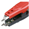
To replace the tip on the L2001, regular size, bundled with the L2001
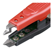
To replace the tip on the L2001, small size
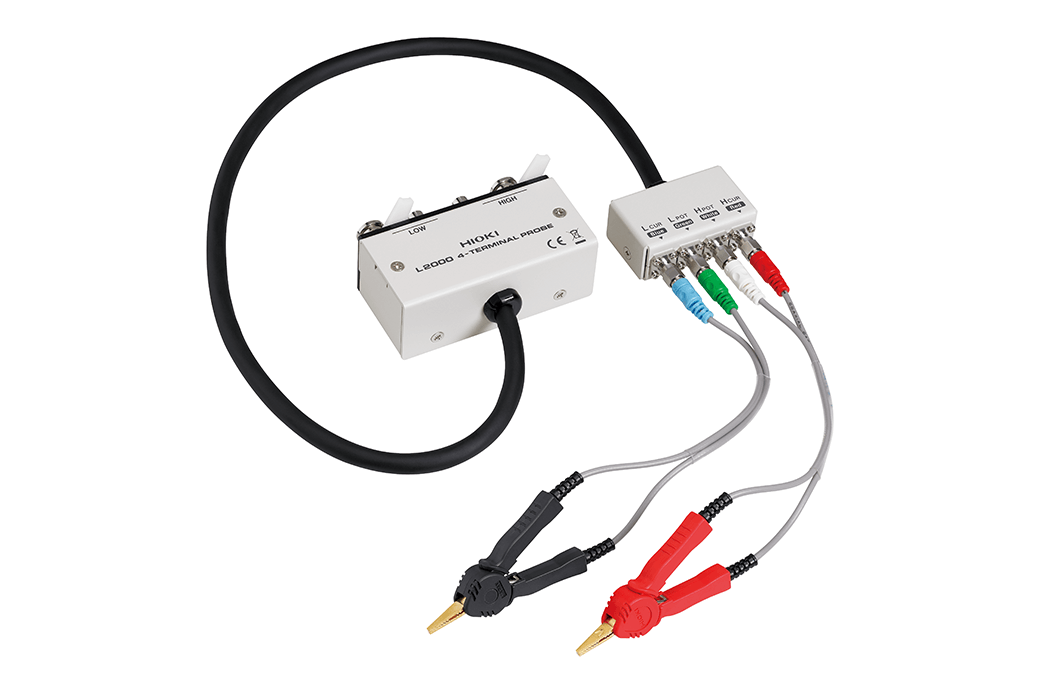
Cable length 1 m (3.28 ft), DC to 8 MHz(Can be measured up to 10 MHz, when combined with the special order model IM3536-01), impedance characteristics of 50 Ω, 4-terminal pair configuration, measurable conductor diameter: ø0.3 (0.01 in) to 5 mm (0.20 in)
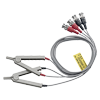
Cable length 1 m (3.28 ft), DC to 200 kHz, impedance characteristics of 50 Ω, 4-terminal pair configuration, measurable conductor diameter: ø0.3 (0.01 in) to 5 mm (0.20 in)
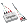
Cable length 1 m (3.28 ft), DC to 8 MHz, impedance characteristics of 50 Ω, 4-terminal pair configuration, measurable conductor diameter: ø0.3 (0.01 in) to 1.5 mm (0.06 in)
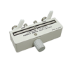
Direct connection type, DC to 8 MHz(Can be measured up to 10 MHz, when combined with the special order model IM3536-01), measurable conductor diameter: ø0.3 (0.01 in) to 2 mm (0.08 in)
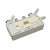
Direct connection type, DC to 8 MHz(Can be measured up to 10 MHz, when combined with the special order model IM3536-01), Test sample dimensions:1 mm (0.04 in) to 10 mm (0.39 in)
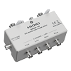
Direct connection type, 40 Hz to 8 MHz, maximum applied voltage of DC ±40 V
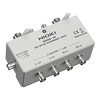
Direct connection type, 40 Hz to 2 MHz, maximum applied current of DC 2 A
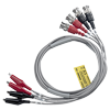
Cable length 1 m (3.28 ft), DC to 200 kHz, impedance characteristics of 50 Ω, measurable conductor diameter: φ0.3 mm (0.01 in) to 2 mm (0.08 in)
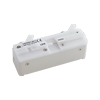
Direct connection type, For measuring SMDs with electrodes on the side; DC to 120 MHz, test sample dimensions: 3.5 mm ±0.5 mm (0.14 in ±0.02 in)
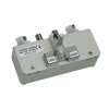
Direct connection type, For measuring SMDs with electrodes on the bottom; DC to 120 MHz, test sample dimensions: 1.0 mm (0.04 in) to 4.0 mm (0.16 in) wide, max. 1.5 mm (0.06 in) high
Factory-installed option (1)
Customers who have purchased the Impedance Analyzer IM3570 can add the Equivalent Circuit Analysis Firmware IM9000 function. Please contact your authorized Hioki distributor or reseller.
PC communication (1)
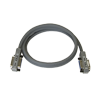
2 m (6.56 ft) length
- Simple Measurement of Semiconductor and Diode C-V Characteristics
- Measurement of DC Voltage Bias Characteristics in Multilayer Ceramic Capacitors (MLCCs)
- Multi-layer Ceramic Capacitors (MLCC)
-
Smart key/immobilizer antenna impedance measurements

-
Pass/Fail Judgment of Passive Components such as Capacitors

-
Test Inductors Characteristics (Coils and Transformers)

-
Test the Characteristics of a Tantalum Capacitor

-
Test the Characteristics of Functional Polymer Capacitors

-
Test the Characteristics of Piezoelectric Elements at High Speeds


